Honda Odyssey 2004. Manual - part 76
−
−
01
01
01
01
01
01
S0X4A000000000J1101PAAT00
Ref. No.
Tool Number
Description
Qty
11-2
Fuel and Emissions Systems
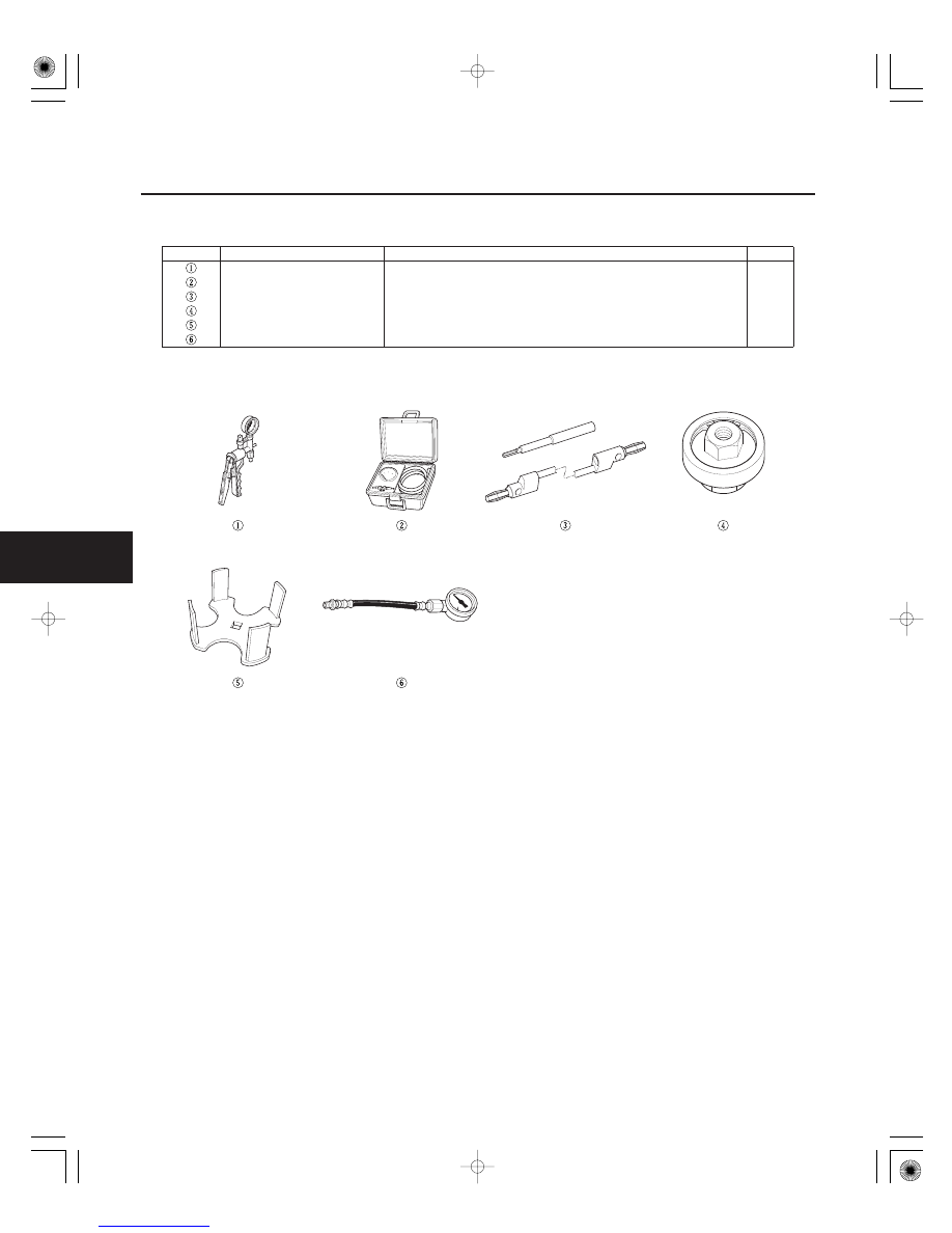
Special Tools
A973X-041-XXXXX
Vacuum Pump/Gauge, 0
30 in.Hg
1
07JAZ-001000B
Vacuum/Pressure Gauge, 0
4 in.Hg
1
07SAZ-001000A
Backprobe Set
2
07VAJ-0040100
Fuel Pressure Gauge Attachment
1
07XAA-001010A
Fuel Sender wrench
1
07406-004000A
Fuel Pressure Gauge
1
03/07/29 09:17:43 61S0X050_110_0002