Honda Element. Manual - part 275


  Index      Honda     Honda Element - service repair manual 2007-2008 year


Search            


Content   ..  273  274  275  276   ..


Honda Element. Manual - part 275


SERVO BODY DISASSEMBLY, INSPECTION, AND REASSEMBLY 

1. Clean all parts thoroughly in solvent, and dry them with compressed air. Blowout all passages.  

2. Inspect the valve body for scoring and damage.  

3. Check shift valve D for free movement. If any fail to slide freely, refer to valve body repair (see VALVE 

BODY REPAIR ).  

4. When removing and installing the shift solenoid valves, refer to shift solenoid valves removal and 

installation (see SHIFT SOLENOID VALVE REMOVAL AND INSTALLATION ).  

5. Coat all parts with ATF during assembly.  

6. Replace the O-rings with new ones. 

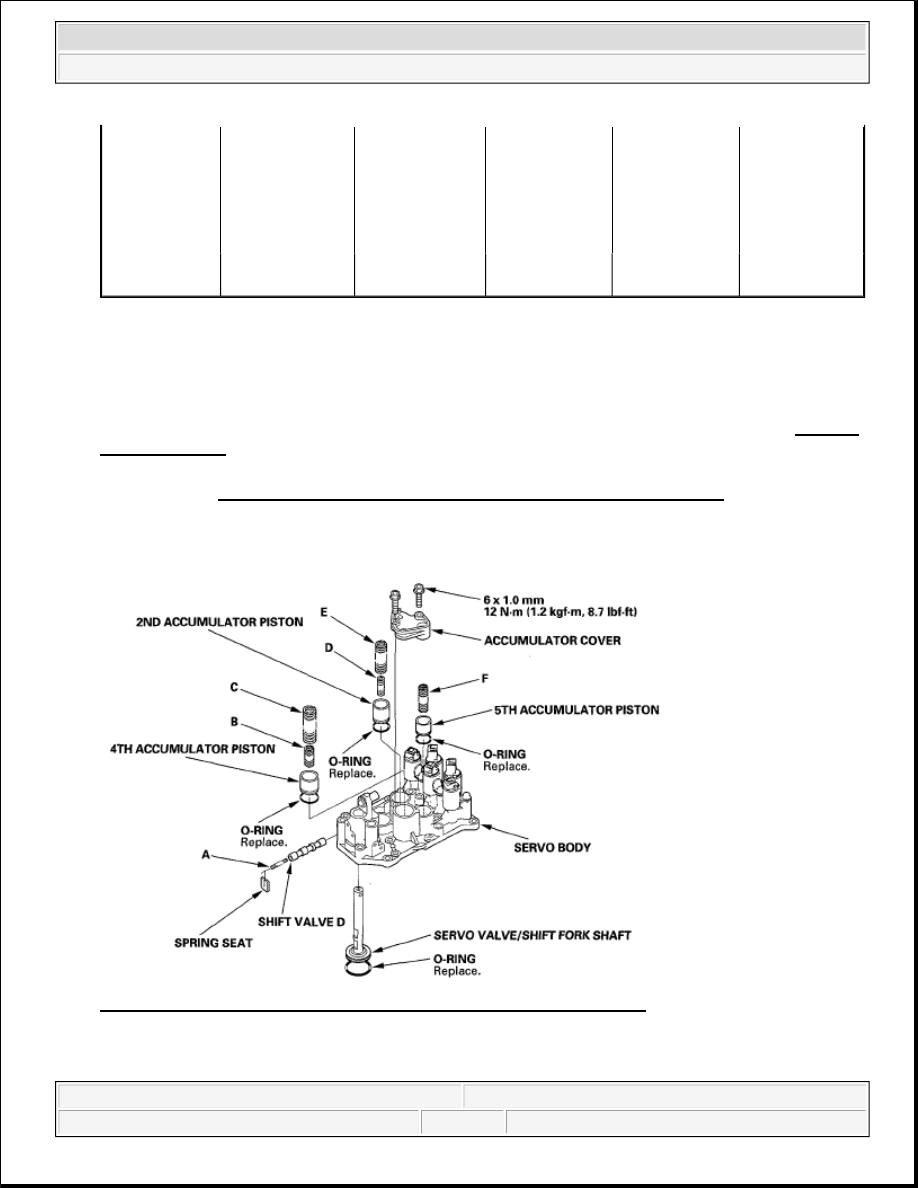
Fig. 437: Disassembled View Of Servo Body With Torque Specification 
Courtesy of AMERICAN HONDA MOTOR CO., INC. 

SPRING SPECIFICATIONS  

E

Lock-up shift 
valve spring

1.0(0.039)

6.6 (0.260)

35.5(1.398)

18.2

F

3rd accumulator 
spring

2.5 (0.098)

14.6(0.575)

29.9(1.177)

4.9

G

1st accumulator 
spring A

2.4 (0.094)

18.6(0.732)

49.0(1.929)

7.1

H

1st accumulator 
spring B

2.3(0.091)

12.2 (0.480)

31.5(1.240)

6.6


2007 Honda Element EX 

2007-2008 TRANSMISSION Automatic Transmission - Element


SPRING SPECIFICATIONS 

SHIFT SOLENOID VALVE REMOVAL AND INSTALLATION 

1. Remove the shift solenoid valves by holding the solenoid valve body.  

2. Install new O-rings (F) on each shift solenoid valves. 

Springs

Standard (New)-Unit: mm (in.)

Wire Diameter

O.D.

Free Length

No. of Coils

A

Shift valve D 
spring

0.8 (0.031)

5.6 (0.220)

28.1 (1.106)

15.9

B

4th accumulator 
spring B

2.3 (0.091)

12.2 (0.480)

31.5 (1.240)

6.6

C

4th accumulator 
spring A

2.4 (0.094)

18.6 (0.732)

49.0 (1.929)

7.1

D

2nd accumulator 
spring B

2.0 (0.079)

10.6 (0.417)

34.0 (1.339)

8.0

E

2nd accumulator 
spring A

2.2 (0.087)

16.6 (0.654)

48.02 (1.898)

8.5

F

5th accumulator 
spring

2.5 (0.098)

14.6 (0.575)

29.9 (1.177)

4.9

NOTE:

Do not hold the shift solenoid connector to remove and to install the shift 
solenoid valves. Hold the shift solenoid valve body.  

Do not install shift solenoid valve A before installing shift solenoid valve 
D, and do not install shift solenoid valve B before solenoid valve E. If 
solenoid valves A and B are installed before solenoid valves D and E, it 
may damage the hydraulic control system.  

NOTE:

New shift solenoid valve comes with new O-rings. If you install a new shift 
solenoid valve, use the O-rings provided on it.


2007 Honda Element EX 

2007-2008 TRANSMISSION Automatic Transmission - Element


Fig. 438: Identifying Shift Solenoid Valve Remove / Install Components With Torque Specifications
Courtesy of AMERICAN HONDA MOTOR CO., INC.
 

3. Install shift solenoid valve D by holding the shift solenoid valve body; be sure to install mounting bracket 

contacts the servo body.  

4. Install shift solenoid valve A by holding the shift solenoid valve body; be sure to install mounting bracket 

contacts the bracket on shift solenoid valve D.  

5. Install shift solenoid valve E by holding the shift solenoid valve body; be sure to install mounting bracket 

contacts the servo body.  

6. Install shift solenoid valve B by holding the shift solenoid valve body; be sure to install mounting bracket 

contacts the bracket on shift solenoid valve E.  

7. Install shift solenoid valve C by holding the shift solenoid valve body; be sure to install mounting bracket 

contacts the servo body.  

MAINSHAFT BEARING AND OIL SEAL REPLACEMENT 

Special Tools Required  

Adjustable bearing puller, 25-40 mm 07736-A01000B or 07736-A01000A  

Driver 07749-0010000  

Attachment, 62 x 68 mm 07746-0010500  

Attachment, 72 x 75 mm 07746-0010600  

1. Remove the mainshaft bearing and oil seal with the adjustable bearing puller and a commercially 

available 3/8 "-16 slide hammer (A). 


2007 Honda Element EX 

2007-2008 TRANSMISSION Automatic Transmission - Element


Fig. 439: Identifying Mainshaft Bearing And Oil Seal With Adjustable Bearing Puller 
Courtesy of AMERICAN HONDA MOTOR CO., INC. 

2. Install the new mainshaft bearing until it bottoms in the torque converter housing with the driver and 62 x 

68 mm attachment. 

Fig. 440: Tapping Mainshaft Bearing 
Courtesy of AMERICAN HONDA MOTOR CO., INC. 

3. Install the new oil seal flush with the housing with the driver and 72 x 75 mm attachment. 


2007 Honda Element EX 

2007-2008 TRANSMISSION Automatic Transmission - Element


Content   ..  273  274  275  276   ..