Honda Element. Manual - part 125


  Index      Honda     Honda Element - service repair manual 2007-2008 year


Search            


Content   ..  123  124  125  126   ..


Honda Element. Manual - part 125


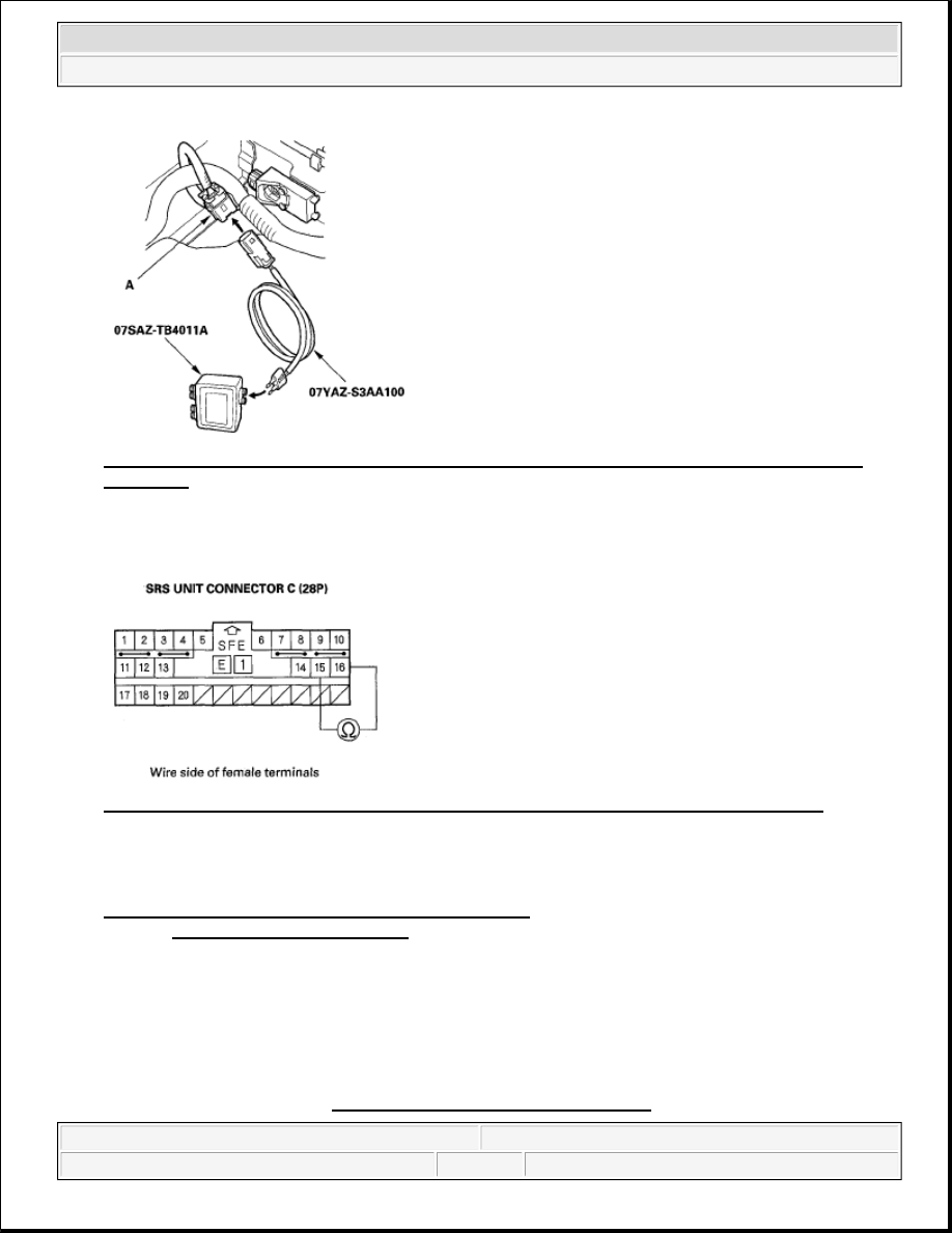
Fig. 156: Connecting SRS Inflator Simulator And Simulator Lead H To Floor Wire Harness 2P 
Connector
 

14. Measure the resistance between the No. 15 and No. 16 terminals of SRS unit connector C (28P). There 

should be 1.0 ohms or less. 

Fig. 157: Measuring Resistance Between SRS Unit Connector C (28P) Terminal 15 And 16 

Is the resistance as specified?  

YES -Faulty right side impact sensor (first) or SRS unit; replace the right side impact sensor (first) (see 
SIDE IMPACT SENSOR (FIRST) REPLACEMENT ). If the problem is still present, replace the SRS 
unit (see SRS UNIT REPLACEMENT ). 

NO -Open in the floor wire harness; replace the floor wire harness. 

DTC 43-2X, 43-3X, 43-BX ("X" CAN BE 0 THRU 9 OR A THRU F): INTERNAL FAILURE OF THE 
LEFT SIDE IMPACT SENSOR (FIRST) 

NOTE:

Before doing this troubleshooting procedure, review SRS Precautions and 
Procedures (see PRECAUTIONS AND PROCEDURES ) and General 


2007 Honda Element EX 

2007-08 RESTRAINTS SRS (Supplemental Restraint System) - Element


1. Clear the DTC memory (see CLEAR THE DTC MEMORY WITH THE HDS ).  

2. Turn the ignition switch ON (II), and check that the SRS indicator comes on for about 6 seconds and then 

goes off. 

Does the SRS indicator stay on, and is DTC 43-2x, 43-3x, or 43-Bx indicated?  

YES -Replace the left side impact sensor (first) (see SIDE IMPACT SENSOR (FIRST) 
REPLACEMENT
 ). If the DTC returns, replace the SRS unit (see SRS UNIT REPLACEMENT ). 

NO -Intermittent failure, system is OK at this time. Go to Troubleshooting Intermittent Failures (see 
TROUBLESHOOTING INTERMITTENT FAILURES ). If another DTC is indicated, troubleshoot 
the DTC. 

DTC 44-2X, 44-3X, 44-BX ("X" CAN BE 0 THRU 9 OR A THRU F): INTERNAL FAILURE OF THE 
RIGHT SIDE IMPACT SENSOR (FIRST) 

1. Clear the DTC memory (see CLEAR THE DTC MEMORY WITH THE HDS ).  

2. Turn the ignition switch ON (II), and check that the SRS indicator comes on for about 6 seconds and then 

goes off. 

Does the SRS indicator stay on, and is DTC 44-2x, 44-3x, or 44-Bx indicated?  

YES -Replace the right side impact sensor (first) (see SIDE IMPACT SENSOR (FIRST) 
REPLACEMENT
 ). If the DTC returns, replace the SRS unit (see SRS UNIT REPLACEMENT ). 

NO -Intermittent failure, system is OK at this time. Go to Troubleshooting Intermittent Failures (see 
TROUBLESHOOTING INTERMITTENT FAILURES ). If another DTC is indicated, troubleshoot 
the DTC. 

DTC 45-1X ("X" CAN BE 0 THRU 9 OR A THRU F): NO SIGNAL FROM THE LEFT SIDE IMPACT 
SENSOR (SECOND) 

Special Tools Required  

SRS inflator simulator 07SAZ-TB4011A  

SRS simulator lead H 07YAZ-S3AA100  

Troubleshooting Information (see GENERAL TROUBLESHOOTING 
INFORMATION ).

NOTE:

Before doing this troubleshooting procedure, review SRS Precautions and 
Procedures (see PRECAUTIONS AND PROCEDURES ) and General 
Troubleshooting Information (see GENERAL TROUBLESHOOTING 
INFORMATION ).


2007 Honda Element EX 

2007-08 RESTRAINTS SRS (Supplemental Restraint System) - Element


1. Clear the DTC memory (see CLEAR THE DTC MEMORY WITH THE HDS ).  

2. Turn the ignition switch ON (II), and check that the SRS indicator comes on for about 6 seconds and then 

goes off. 

Does the SRS indicator stay on, and is DTC 45-1 x indicated?  

YES -Go to step 3. 

NO -Intermittent failure, system is OK at this time. Go to Troubleshooting Intermittent Failures (see 
TROUBLESHOOTING INTERMITTENT FAILURES ). If another DTC is indicated, troubleshoot 
the DTC. 

3. Turn the ignition switch OFF. Disconnect the negative cable from the battery, and wait for 3 minutes.  

4. Check the connections at C551, C652, C603, C602 and the floor wire harness 2P connector at the left side 

impact sensor (second). 

Is the connection OK?  

YES -Go to step 5. 

NO -Repair the poor connection and retest. If DTC 45-1x is still present, go to step 5. 

5. Disconnect the floor wire harness 2P connector (A) from the left side impact sensor (second). 

Fig. 158: Identifying Floor Wire Harness 2P Connector 

6. Disconnect SRS unit connector C(28P) from the SRS unit (see step 9 on ).  

7. Measure the resistance between the No. 17 and No. 18 terminals of SRS unit connector C (28P). There 

should be an open circuit or at least 1 M ohms. 

NOTE:

Before doing this troubleshooting procedure, review SRS Precautions and 
Procedures (see PRECAUTIONS AND PROCEDURES ) and General 
Troubleshooting Information (see GENERAL TROUBLESHOOTING 
INFORMATION ).


2007 Honda Element EX 

2007-08 RESTRAINTS SRS (Supplemental Restraint System) - Element


Fig. 159: Measuring Resistance Between SRS Unit Connector C (28P) Terminal 17 And 18 

Is the resistance as specified?  

YES -Go to step 8. 

NO -Short in the floor wire harness, dashboard wire harness A, or the roof wire harness; replace the 
faulty harness. 

8. Measure the resistance between the No. 17 terminal of SRS unit connector C (28P) and body ground, and 

between the No. 18 terminal and body ground. There should be an open circuit or at least 1 Mohms. 

Fig. 160: Measuring Resistance Between SRS Unit Connector C (28P) Terminal 17 And Body 
Ground
 

Is the resistance as specified?  

YES -Go to step 9. 

NO -Short to ground in the floor wire harness, dashboard wire harness A, or the roof wire harness; 
replace the faulty harness. 

9. Reconnect the negative cable to the battery.  

10. Turn the ignition switch ON (II).  


2007 Honda Element EX 

2007-08 RESTRAINTS SRS (Supplemental Restraint System) - Element


Content   ..  123  124  125  126   ..