Great Wall Florid. Manual - part 54


  Index      Great Wall     Great Wall Florid - service repair manual 2008 year


Search            copyright infringement  


Content   ..  52  53  54  55   ..


Great Wall Florid. Manual - part 54


GWFLORID Maintenance Manual

214

Areas of Importance

1.  While performing maintenance on the SRS airbag, make sure to work in accordance with this 

chapter's steps and notes.

2.  Be sure to use the specified test apparatus and SST (Special Service Tools) which are mentioned in this 

chapter.

3.  While performing maintenance on the following mentioned components, if there is any problem with a 

component, be sure to replace it with a new one.

• Airbag ECU assembly.

• Clock spring assembly.

• Driver side airbag assembly.

• Front passenger side airbag module.

• Driver side preload seat belt.

• Front passenger side preload seat belt.

• Airbag wire harness.

4.  While performing maintenance, please disconnect the battery's negative terminal connector, and then 

after waiting for 60 s, commence operation. Furthermore, wrap up the removed negative terminal with 

insulating tape.

After the battery power is cut off, the capacitor in the airbag ECU will still maintain a set amount of electrical 

energy. If used without waiting a sufficient amount of time, it may lead to serious injury and accidents due to 

the airbag's faulty deployment.

5.  When painting the vehicle, excessive heat may influence the components, in which case the SRS-ECU, 

airbag module, clock spring, etc., should first be removed and set aside.

Use a diagnostic scanner to clear the trouble code after the SRS airbag is repaired, as to ensure the warning 

lamp will continue to work normaly.

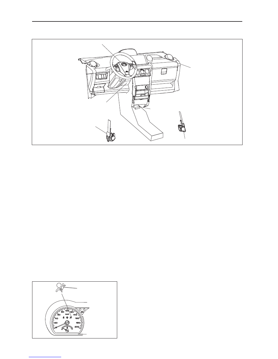
Airbag Electronic Control Unit

Airbag warning lamp

Airbag ECU assembly 2

Front passenger side 

airbag assembly

Driver side airbag assembly

Diagnostic interface position

Driver side electronic pretensioner

Front passenger side electronic pretensioner

The position of the airbag warning 
lamp inside the combination meter

215

Airbags

Airbag electronic control interface and interface-pin definition

No. 

Name

Description

1

DRV A/B +  

Driver side airbag assembly, high end 

2

DRV A/B -

Driver side airbag assembly, low end 

3

PSG A/B +

Front passenger side airbag assembly, high end

4

PSG A/B -

Front passenger side airbag assembly, low end

7

PSG PRETENSIONER - Front passenger seat belt pretensioner, low end

8

DRV PRETENSIONER + Driver seat belt pretensioner, high end 

9

DRV PRETENSIONER - Driver seat belt pretensioner, low end

10

WARNING LAMP

Warning lamp

11

GND

Ground cable

25

BPT Hi 

ON power supply

30

PSG PRETENSIONER - Front passenger seat belt pretensioner, high end

46

K-LINE

Serial data I/O (K wire) diagnosis

Diagnostic Scanner

Instrument

Name

Application

X-431 diagnostic scanner

Check the system malfunction 

of the SRS airbag system and 

clear the ECU trouble code.

GWFLORID Maintenance Manual

216

SRS airbag warning lamp inspection

1.  When the ignition switch is set to the ON position, check if the SRS warning lamp remains on for 6-7 s.

2.  If the SRS warning lamp shuts off after 6-7 s, this is normal.

3.  Except for the items listed above, diagnostic inspection is still needed.

System diagnosis

Airbag ECU will initiate a series of diagnostic test cycles to check if the airbag system functions are ready for 

use. This diagnostic test can guard against the restraint system's faulty execution and at the same time guarantee 

prompt execution in a collision. If a malfunction appears, airbag ECU will store the appropriate trouble code and 

light up the warning lamp to point out the malfunction, as to make maintenance more convenient.

Diagnostic interface

Troubleshooting

Basic processes of the malfunction diagnostic

There are two SRS-ECU malfunctions types classified by time: current malfunction and history malfunction. 

The malfunction types categorized by property are: external malfunction and internal malfunction.

Current malfunction trouble codes and history malfunction trouble codes may exist at the same time. External 

malfunction trouble codes can be eliminated with a diagnostic instrument, but the internal malfunction trouble 

codes cannot be cleared unless the SRS-ECU is changed.

Caution: After installing a new SRS airbag system electronic control unit, the airbag system warning 

lamp will remain on for 6-7 s when the ignition switch is set to the ON position. This indicates that 

the SRS airbag is operating properly. At this point, the system does not need to be inspected and 

repaired. Aside from this case however, the system should be diagnosed and repaired.


Warning lamp

abnormal 

Connect the scanner

and K wire to 

scan the ECU

Detected fault

Troubleshooting 

Clear the 

trouble codes


217

Airbags

Malfunction judgment 

1.  Malfunction record (trouble code storage)

After the ECU performs the diagnostic test cycle in order to verify a malfunction, the SRS-ECU will store the 

relevant code, the initial detection time, the final detection time, and the number of times it occurred in the 

EEPROM.

The SRS-ECU can store 16 codes at most.

2.  SRS-ECU approved trouble codes

No.

Malfunction introduction

Type code

Trouble 

code

Possible 

removal

1

(Front passenger side preload seat belt), connected to the 

power supply

03H

01H

Removable

2

(Driver side front row preload seat belt), connected to the 

power supply

03H

02H

Removable

3

(Driver side airbag assembly), connected to the power 

supply

03H

03H

Removable

4

(Front passenger side airbag assembly), connected to the 

power supply

03H

04H

Removable

5

(Front passenger side seat preload seat belt), grounded

02H

01H

Removable

6

(Driver side front row preload seat belt), grounded

02H

02H

Removable

7

(Driver side airbag assembly), grounded

02H

03H

Removable

8

(Front passenger side airbag assembly), grounded

02H

04H

Removable

9

(Front passenger side preload seat belt), resistance too 

high or open circuit

01H

01H

Removable

10

(Driver side front row preload seat belt), resistance too 

high or open circuit

01H

02H

Removable

11

(Driver side airbag assembly), resistance too high or open 

circuit

01H

03H

Removable

12

(Front passenger side airbag assembly), resistance too 

high or open circuit

01H

04H

Removable

13

(Front passenger side preload seat belt), resistance too 

low or short circuit

0CH

01H

Removable

14

(Driver side preload seat belt), resistance too low or short 

circuit

0CH

02H

Removable

15

(Driver side airbag assembly), resistance too low or short 

circuit

0CH

03H

Removable

16

(Front passenger side airbag assembly), resistance too 

low or short circuit

0CH

04H

Removable

17

Power supply voltage is out of range (high voltage or low 

voltage)

12H

42H

Removable

18

Power cord contact dysfunctional

11H

42H

Removable

19

Warning lamp fault - connected to the power supply or 

bulb is short circuited

03H

40H

Removable

20

Warning lamp fault - grounded or open circuit in filament

02H

41H

Removable

21

Configuration error

06H

44H

Removable

22

Internal malfunction

0DH

>80H

Irremovable

Replace 

airbag ECU

Trouble code transmission is completed the SRS-ECU outputs through the maintenance program's 

serial data interface to the specified diagnostic instrument (X-431 diagnostic scanner).

3.  Internal malfunction

The microcontroller can detect the following items not only when starting up detection, but also during the 

diagnostic detection cycle.

(a)  The ignition circuit triggers the transistor: The high-end transistor will be detected not only when starting up 


Content   ..  52  53  54  55   ..