Geely Emgrand X7. Manual part - 530


  Главная      Geely     Geely Emgrand X7 - Manual


поиск по сайту            


содержание   ..  529  530  531  ..


Geely Emgrand X7. Manual part - 530


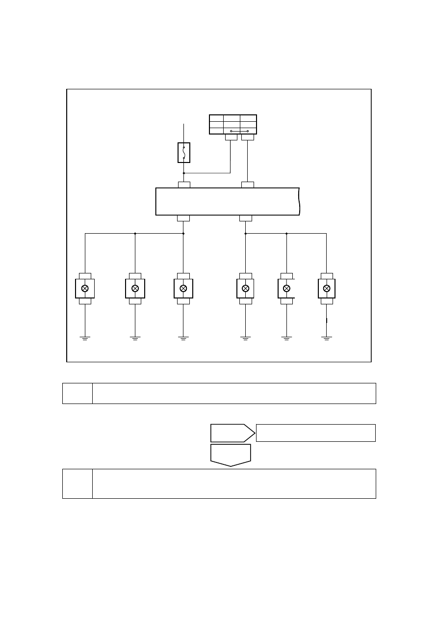
11.4.7.13 Hazard warning lamp do not work 

Circuit diagram: 

NL11-4049b

D DR08

G DR08

6 SO31

3 SO31

8 CA12

8 IP48

6 IP50

7 IP48

9 IP48

5 CA12

8 CA18

5 CA18

6 SO24

3 SO24

D DR18

G DR18

10A

IF04

1 IP07 4 IP07 3

OFF

ON

1

4

左后视镜
(左侧转向灯)

左后组合灯
(左转向灯)

左前组合大灯
(左转向灯)

右前
组合大灯
(右转向灯)

右后组合灯
(右转向灯)

右后视镜
(右侧转向灯)

危险警告
开关

BCM

TURN-LH LAMP

TURN-RH LAMP

HAZARD

P-TURN LAMP


Diagnostic steps: 

Confirm whether the steering work light is normal. 

(a)  Ensure whether turning lamp works normally. 


Repair the circuit from the fuse IF04 to the terminal No. 1 of the hazard warning switch 
IP07. 

(a)  Rotated ignition switch to "OFF" position. 

(b)  Disconnect hazard warning lamp switch harness connector. 

(c)  Measure resistance between fuse IF04 to danger warning lamp switch wire harness connector 

IP07 terminal No. 1. 

Standard resistance: less than 1 Ω 

No 

See 11.3.7.12 steering lamp does not work.

Yes 

Hazard 
warning 
switch 

Left rearview 
mirror ( left 
side steering 
lamp) 

Left rear 
combination 
lamp (left 
steering lamp) 

Left front 
combination 
headlamp (left 
steering lamp)

Right front 
combinatio

headlamp 
(right 
steering 
lamp)

Right 
rearcombin
ation lamp 
(right 
steering 
lamp) 

Right 
rearview 
mirror (right 
side steering 
lamp) 

2119

Confirm if the resistance conforms to 
standard value. 

NL11-4039b

IR05

8 5

8 6

8 7

3 0

IR02

8 5

8 6

8 7

3 0

IR07

8 5

8 6

8 7

3 0

4

IR01

2

1

5

3

4

2

1

5

3

IR04

IR03

8 5

8 6

8 7

3 0

IF 1 4

IF
2

9

IF
3

2

IF
3

3

IF
3

4

IF
3

5

IF
1

8

IF 2 0

IF 11

IF
2

5

IF
2

6

IF
2

7

IF
2

5

IF
0

1

IF
0

2

IF
0

3

IF
0

4

IF
0

5

IF
0

6

IF
2

6

IF
2

7

IF
2

3

IF

30

IF

1

2

IF

1

6

IF

1

7


NL11-4050b

IP07 危险警告灯开关线束连接器

2

6

5

4

3

1

1


Inspect the grounding voltage of the terminal No. 4 of the hazard warning lamp switch 
wire harness connector IP07. 


No 

Repair or replace the harness. 

Yes 

IP07hazard warning lamp 

switchharness connector 

2120

(a)  Connect danger warning lamp 

switch wire harness connector. 

(b) Open 

hazard warning lamp 

switch. 

(c)  Measure grounding voltage of 

danger warning switch wire 
harness connector IP07 terminal 
No. 4. 

Standard voltage: 11-14 V 

Confirm if the voltage conforms to 
standard value. 

NL11-4051b

IP07 危险警告灯开关线束连接器

2

6

5

4

3

1

4


Repair the wire harness between the terminal No. 4 of the hazard warning lamp switch 
wire harness connector IP07 and the terminal No. 6 of the BCM wire harness connector 
IP50. 


(a)  Rotated ignition switch to "OFF" 

position. 

(b) Separately 

disconnect 

danger 

warning lamp wire harness 
connector and vehicle body 
control module wire harness 
connector 4. 

(c)  Measure resistance between 

warning lamp switch IP07 
terminal No. 4 and vehicle body 
control module wire harness 
connector 4 IP50 terminal No. 6. 

Standard resistance: less than 1 Ω 

Confirm if the resistance conforms to 
standard value. 

NL11-4051b

IP07 危险警告灯开关线束连接器

2

6

5

4

3

1

4

No 

Replace hazard warning lamp switch, Refer 
to11.3.8.17 replace hazard warning lamp switch. 

Yes 

IP07hazard warning lamp 

switchharness connector 

IP07hazard warning lamp 

switchharness connector 

2121


NL11-4052b

IP50 车身控制模块线束连接器4

1

2

3

4

5

6

7

8

9 10 11 12 13 14 15 16 17 18 19 20

21 22 23 24 25 26 27 28 29 30 31 32 33 34 35 36 37 38 39 40

6


Replace the BCM 

(a)  Replace BCM and refer to Replacement of BCM in 11.8.8.1. 

Confirm the completion of repair. 


16 

The system is normal. 


Next 

No 

Repair or replace the harness. 

Yes 

IP50body control module harness 

connector4 

2122


содержание   ..  529  530  531  ..