Geely Emgrand X7. Manual part - 504


  Главная      Geely     Geely Emgrand X7 - Manual


поиск по сайту            


содержание   ..   501  502  503  504  505 ..


Geely Emgrand X7. Manual part - 504


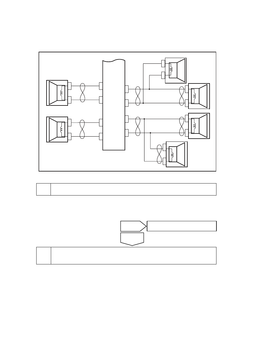
11.2.6.4 Audio head unit can be turned on but the speakers are inoperative 

Circuit diagram: 

NL11-2009b

B

A

BA

BA

BA

AB

4

IP

2

2

DR

17

DR17

DR16

DR16

DR22

DR

2

2

DR

3

2

DR32

DR06

DR06

BA

DR07

DR07

3

IP

22

8
IP
2

2

7
IP
22

2
IP
22

1
IP
22

5

IP

22

6

IP

2

2

FR-

右高音扬声器

右前门扬声器

左后门扬声器

右后门扬声器

左前门扬声器

左高音扬声器

收放机

RL-

RL+

RP-

RP+

FL+

FL-

FR+


Diagnostic steps: 

Operate the audio unit. 

A.  Operate the audio head unit master control panel,adjust the channel, so that front and rear and 

left and right channels are in the middle. 

Confirm whether all the speakers are inoperative? 


Inspect audio output of the audio wire harness connector IP22 and the grounding 
resistor. 


No 

Go to step 4 

Yes 

Right reardoor 

speaker 

Left rear door 

speaker 

Radio-cassette 

player 

Lefthigh-pitch speaker 

Left front door 

speaker 

Right front door speaker 

Righthigh-pitch speaker 

2015

(a)  Dismantle main host of sound 

equipment. 

(b)  Disconnect audio main machine 

harness connector IP22. 

(c)  Use multimeter to measure 

resistance between all audio 
output terminal of wire harness 
connector IP22 of main host of 
sound equipment and grounding. 

Standard resistant value :10 KΩ or 
higher 

Confirm if the resistance conforms to 
standard value. 

NL11-2010b

7

5

3

1

2

8

6

4

IP22 收放机线束连接器2

7

5

3

1

2

8

6

4


Repair the short circuit fault between the audio head unit wire harness connector IP22 
and the body grounding. 

A. Confirm that the open circuit between Terminal 5 of the harness connector IP22 of the audio 
unit and ground wire of the body is fixed. 

Confirm whether the radio is working correctly. 


Inspect the loudspeaker circuit that does not work. 


A.  Dismantle audio main machine 

harness connector IP22 

B.  Measure the resistance of the 

loudspeaker from the harness 
connector IP22 with a universal 
meter. 

NL11-2010b

7

5

3

1

2

8

6

4

IP22 收放机线束连接器2

7

5

3

1

2

8

6

4


Yes 

Go to step 8 

No 

Yes 

The system is normal. 

No 

Go to step 8 

IP22 Radio-cassette player 

harness connector2 

IP22Radio-cassette player 

harness connector2 

2016

Standard Resistance 

Test speakers 

Test terminal 

Standard 

resistance 

Left rear speaker 

Instrument harness connector IP22-No 8, 7 

terminal 

4Ω 

Right rear loudspeakers 

Instrument harness connector IP22-No 2, 1 

terminal 

4Ω 

Left front door window 

high pitch speaker 

Instrument harness connector IP22-No 5, 6 

terminal 

2-3Ω 

Driver door speaker 

Instrument harness connector IP22-No 5, 6 

terminal 

2-3Ω 

Right front door and 

window high-pitch 

speaker 

Instrument harness connector IP22-No 4, 3 

terminal 

2-3Ω 

Driver door speaker 

Instrument harness connector IP22-No 4, 3 

terminal 

2-3Ω 

Confirm whether the resistance is normal. 


Inspect the open circuit fault between the loudspeaker circuits. 


(a)  Disconnect audio main machine 

harness connector IP22. 

(b)  Disconnect the inoperative 

speaker connector. 

(c)  According to the following items, 

use multimeter to measure 
connetor terminal of speaker 
which doesn't work. 

NL11-2011b

A

B

DR22/32 后扬声器线束连接器

Yes 

Go to step 7 

No 

DR22/32rear speaker harness 

connector 

2017


NL11-2012b

DR07/17 前门高音扬声器线束连接器

A

B

A

B


NL11-2013b

A

B

DR06/16 前门扬声器线束连接器


Position Multimeter 

connection 

Specified 

conditions 

Left rear 

speaker 

Terminals A and B of door wire harness connector DR22 and 
the instrument wire harness connector respectively 
IP22 No. 7. 8 terminal 

Less than 1 Ω 

Right rear 

loudspeakers 

Terminals A and B of door wire harness connector DR32 and 
the instrument wire harness connector respectively 
IP22 No 1. 2 terminal 

Less than 1 Ω 

Left front door 

window high 

pitch speaker 

Terminals A and B of door wire harness connector DR07 and 
terminal No. 5 and 6 of instrument wire harness connector 
IP22 

Less than 1 Ω 

Right front 

door and 

window 

high-pitch 

speaker 

Terminals A and B of door wire harness connector DR17 and 
terminal No. 4 and 3 of instrument wire harness connector 
IP22 

Less than 1 Ω 

Driver door 

speaker 

Terminals A and B of door wire harness connector DR06 and 
terminal No. 5 and 6 of instrument wire harness connector 

Less than 1 Ω 

DR07/17front doorhigh-pitch speaker 

harness connector 

DR06/16 front door speaker harness 

connector 

2018


содержание   ..   501  502  503  504  505 ..