Geely Emgrand X7. Manual part - 215


  Главная      Geely     Geely Emgrand X7 - Manual


поиск по сайту            


содержание   ..  212  213  214  215  216  ..


Geely Emgrand X7. Manual part - 215


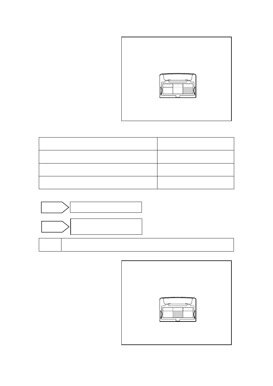
E.  Measure resistance between the 

vehicle speed sensor harness 
connector EN21 terminal No.3 
and a reliable ground. Inspect 
whether the circuit is short to 
ground. 

F.  Measure voltage between the 

vehicle speed sensor harness 
connector EN21 terminal No.3 
and reliable ground with 
multimeter. Inspect whether the 
circuit is short to power supply. 

NL02-2117b

1

2

3

EN21 车速传感器线束连接器

3


Tester Connection 

Standard Value 

EN21(3)-EN01(51) resistance 

Less than 1 Ω 

Resistance Between EN21 (3) and Ground 

10 kΩ or higher 

Voltage Between EN21 (3) and Ground 

0V 

Are the values specified values? 


Inspect the vehicle speed sensor ground circuit. 


A.  rotated ignition switch to OFF 

position. 

B.  Disconnect speed sensor harness 

connector EN21. 

C.  Rotated ignition switch to ON 

position  . 

(d)  Measure the resistance between 

vehicle speed sensor harness 
connector EN21 terminal No.2 
and a reliable ground. 

Standard Value: Less than 3 Ω 

NL02-2120b

1

2

3

EN21 车速传感器线束连接器

2

No 

Repair or replace the wire harness 
connector to step 8. 

Go to step 7 

Yes 

EN21 speed sensor harness connector 

EN21 speed sensor harness connector 

859

Is the value specified value? 


Replace the vehicle speed sensor. 


Inspect the ECM Power Supply Circuits. 

A.  Inspect whether ECM power supply circuit is normal. 

B.  Inspect whether ECM ground circuit is normal. 


7 Replace 

ECM 

A.  Refer to 2.12.7.11 Crankshaft Position Sensor (CKP) Learn to carry out the crankshaft 

position sensor learn after replacing the ECM. 


Use a fault diagnosis tester to confirm whether the DTC Code is stored again. 

A.  Connect fault diagnosis tester to the data link connector. 

B.  Rotated ignition switch to ON position. 

C.  Clear DTC code. 

D.  Start and run the engine at idle speed to warm up the engine for at least 5min. 

E.  Read control system DTC code again to confirm that the system has no DTC code exported. 


9 Troubleshooting 

5. Maintenance 

guide 

Refer to 3.3.6.2 Replacement of Vehicle Speed Sensor to replace the vehicle speed sensor. 

No 

Intermittent fault refers to 2.12.7.3 List of 
Intermittent Fault. 

Yes 

Next 

No 

Repair the faulty part. 

Yes 

No 

Repair or replace the wire harness 
connector to step 7. 

Yes 

Next 

Go to step 8 

860

2.12.7.42 DTC P0506 P0507   

1. DTC 

description: 

DTC  P0506 

Idle Speed Too Low 


DTC  P0507 

Idle Speed Too High 

Throttle actuator control motor is controlled by the engine control module (ECM). Internal DC 
motor drives throttle body. In order to reduce idle speed and adjust the spark and fuel supply, 
engine control module commands the throttle to close. By reducing the air flow into the engine, 
idle speed is lowered. In order to improve idle, the engine control module commands the throttle 
to open, so that more air flows through the throttle. 

Engine control module (ECM) calculates and controls engine idle speed based on coolant 
temperature, speed compensation, reducing speed, Air-Conditioning compensation and voltage 
compensation. 

2.  Conditions For Setting DTC and The Fault Location: 

DTC 
Code 

DTC Detection 
Strategy 

Conditions For Setting The DTC 
(Control Strategy) 

Fault Locations 

P0506 

Idle speed is 
lower than the 
target speed by 
100 rpm 

1.  The engine is at idle speed. 

2.  The vehicle speed is equal to 0. 

3.  Engine coolant temperature is more 

than 60℃(140ºF) 

4.  Duration is longer than 10s. 

P0507 

Idle speed is 
higher than the 
target speed by 
200 rpm 

1.  The engine is at idle speed. 

2.  The vehicle speed is equal to 0. 

3.  Engine coolant temperature is more 

than 60℃(140ºF) 

4.Duration Longer Than 10s. 

1. ETC 

throttle 

body 
assembly 

2. Intake 

System 

3   Exhaust 

System 

4. ECM 

3. Diagnostic 

Steps: 

Note: Before carrying out this diagnosis step, observe the data list on fault diagnosis tester and 
analyze the accuracy of the data, as these will help with quick diagnosis. 

Inspect whether there are control system DTC codes other than DTC P0506 P0507. 

A.  Connect fault diagnosis tester to the vehicle diagnostic interface. 

B.  Rotated ignition switch to ON position    . 

C.  Press the power button of fault diagnosis tester. 

D.  Select the following menu items: Engine/Read DTC codes. 

E.  Read DTC codes. 

861

Results 

DTC Codes Shown 

To Step 

DTC P0506 P0507 

No 

DTC code other than P0506 P0507 

Yes 


Inspect whether generator is working properly. 

A.  Use a fault diagnosis tester to observe whether the system voltage parameters are normal. Is 

generator generating capacity normal? 


Inspect intake air pressure sensor parameters. 

A.  Use a fault diagnosis tester to observe whether system intake air pressure sensor parameters 

are correct. Refer to 2.12.7.9 Data Flow Table. Are intake air pressure sensor parameters 
normal? 


Inspect the working condition of the air-conditioner. 

A.  Use a fault diagnosis tester to observe whether the air-conditioning working status is 

consistent with the actual air-conditioning working condition. Refer to 2.12.7.9 Data Flow 
Table. 

When the air-conditioning is switched on and the pressure switch voltage is greater than 0 V, does 
the idle speed increase by about 150 rpm? 


Inspect air intake system and exhaust system. 

A.  Inspect air intake system and exhaust system for blockage and air leakage. 

B. Too 

much 

carbon 

residue in throttle. 

Yes 

Go to step 7 

No 

No 

Repair generator fault. 

Yes 

No 

Repair generator fault. 

Yes 

Yes 

Refer to 2. 3.6.11 DTC Chapter Index. 

No 

862


содержание   ..  212  213  214  215  216  ..