Geely Emgrand X7. Manual part - 147


  Главная      Geely     Geely Emgrand X7 - Manual


поиск по сайту            


содержание   ..   144  145  146  147  148  ..


Geely Emgrand X7. Manual part - 147


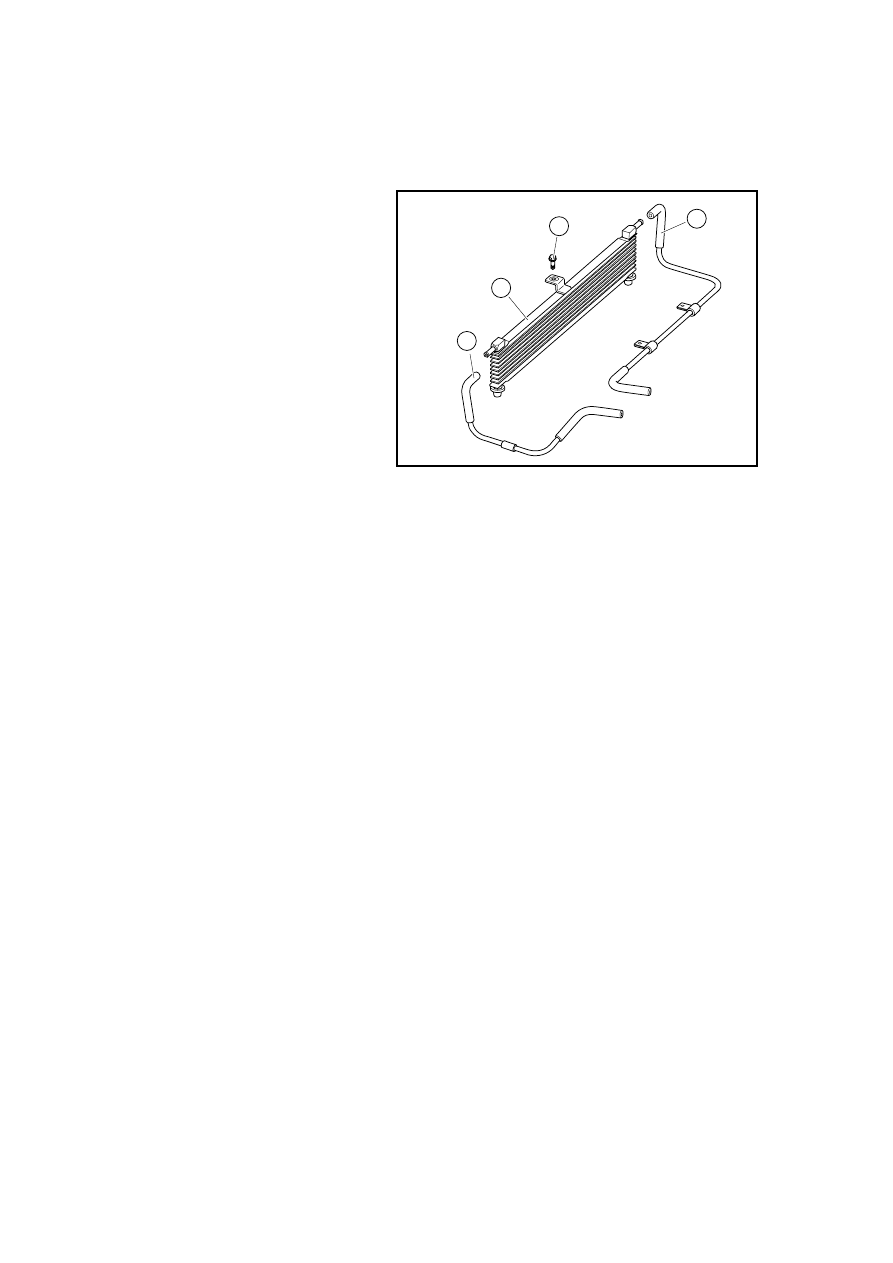
2.8.8.6 oil cooler replacement (with DSIAuto-transmission ) 

Dismantlement Procedure 

1.  Disconnect the battery negative 

electrode cable. 

Refer 

to 

2.12.6.1 Battery Disconnection. 

2. For drainage of automatic 

transmission oil, refer to 3.4.7.3 
Replacement procedures of 
automatic transmission oil. 

3.  Dismantle oil cooler oil inlet 

hose 1 . 

4.  Dismantle oil hose 2 of oil 

cooler. 

3.  Dismantle oil cooler assembly 

fixing bolt 3 . 

4.  Dismantle oil cooler assembly 4. 

Installation Procedure: 

1.  Install oil cooler and tighten 

fixing bolt. 

2.  Connect oil inlet and outlet hose 

of oil cooler. 

3.  Filled Auto-transmission oil  . 

2

1

3

4

NL02-2002c

587

2 . 9 Lubrication system (4G20/4G24) 

2.9.1 Specifications 

2.9.1.1 Fastener specifications 

Specification 

Fastener Name 

Model 

Metric (N.m) 

English system 
(lbf-ft) 

Oil Pan and Crankcase Connecting 
Bolts 

M6×14 7-11 5-8 

Purge cock 

M12×1 . 25×10 . 5 

33-37 

25-28 

Oil Filter Adapter 

M24×1 . 5×17 

27-33 

19-24 

Oil Filter Components 

UNF3/4 

17-23 

12-16 

Piston injector component and 
cylinder block 

Connecting Bolts 

M6×12 6-8 4-6 

Oil pump component and oil 
strainer component 

Connecting Bolts 

M6×30 7-11 5-8 

Oil pump component and crankcase 

Connecting Bolts 

M8×65 17-21 

12-15 

Oil Pump Mounting Bolt 

M6×14 

7-11 

5-8 


2.9.1.2 Oil Pump Specification 

Side Clearance 

0.05~0.10mm(0.0020~0.0039in) 

Tooth Clearance 

0.08~0.18mm(0.0031~0.0071in) 

Oil pressure alarm device activation pressure ≤40kPa(≤6psi) 

Oil Pump Output Pressure 

0.77MPa (111.7psi) 

Oil Pump Relief Valve Opening Pressure 

0.40~0.50MPa(57.8~72.2psi) 


588

2.9.2 Description and Operation 

2.9.2.1 Description and operation 

Oil Pan 

The oil pan is installed at the bottom of the crankcase. The engine oil pump draws engine oil from 
the oil pan. After filtered by the oil filter, the engine oil passes through two oil paths within the 
main oil path. The upper oil path heading to the cylinder block and cylinder hood cover 
lubricating the relevant friction pairs and components; while the lower oil path heading to the 
balance shaft, lubricating its friction pairs. In the main oil path, it has not only five main bearing 
lubrication paths but also four piston injector components. The five main bearing lubricant paths 
lubricate the main bearing. The oil is injected to the connecting rod through the engine oil path in 
the crankshaft to lubricate the connecting rod bearing; the piston injector components take on 
pump cooling for the pump. In the upper oil path, the engine oil passes through the oil orifices in 
the cylinder body and cylinder hood cover and heads to the camshaft (including OCV valve). The 
engine oil passes the internal oil path within the camshaft, lubricating valve assembly, and then 
finally returns to the oil pan. 

Oil Pump 

Oil pump draws the engine oil from the oil pan and then pump the engine oil with pressure to the 
various parts of the engine. Oil pump inlet has an oil filter - set filter. Set filter blockage may 
damage the oil pump and cause the pump oil inoperative, and the lubricating system will be 
unable to establish a normal oil pressure, which will cause the engine mechanical damage. Oil 
pump is driven by the crankshaft concave. As long as the crankshaft rotates, the oil pump will be 
working. The oil pump displacement is fixed, so when the engine speed is high, the oil pump 
output pressure will exceed the needs of the engine lubrication system. There is a safety valve in 
the oil pump assembly. The safety pressure relief valve cavity is connected with the oil pump 
intake chamber. When the output pressure exceeds 0.40~0.50 MPa (57.8~72.2psi), the security 
valve is open, the excess oil returns to the oil pump through the valve. With the normal oil supply, 
the safety valve bypass is closed. 

Lubrication Descriptions 

The oil filter is installed at the bottom of the crankcase. The engine oil passes through the internal 
oil path within the crankcase and heads to the filter. After filtering, the engine oil passes through 
the internal oil path within the crankcase and heads to the cylinder body and balance shaft, etl. The 
engine oil flows into the cylinder hood cover through the frontal oil path of the cylinder body. The 
cylinder hood cover oil path is divided into the camshaft and VVT oil path, respectively supplying 
the oil for the intake and exhaust camshaft lubrication, as well as the control over the OCV and 
VVT. 

Each cylinder hood oil path introduces engine oil into the cylinder hood cover and camshaft 
bearing journal. Engine oil passes through the main oil path to the VVT solenoid valve, VVT 
solenoid valve oil cavity, to the VVT actuator. VVT solenoid valve is used to control intake 
camshaft position actuator. Engine Control Module (ECM) controls the VVT solenoid valve. 
When the engine control module provides power to the VVT solenoid valve, the solenoid valve 
guides the engine oil to flow through the cylinder hood cover camshaft front bearing caps. Engine 
oil passes through the intake camshaft bearing caps into the camshaft journal drilled hole and 
flows to the intake camshaft front installation surface. Then, the engine oil flows to the camshaft 
position actuator corresponding oil path. VVT solenoid valve guides engine oil into the system 
corresponding oil path, so that the engine oil pressure acting on the intake camshaft position 
actuator internal blades. The intake camshaft (installed on the camshaft position actuator inner 
rotor) rotates relative to the sprocket (mounted on the intake camshaft position actuator housing). 
At idle, the internal pin will lock the rotor to the intake camshaft actuator housing. When starting, 
the cam actuator position will maintain the original position or the default position. VVT solenoid 
valve guides engine oil hydraulic pressure to loosen the lock pin, so that the intake camshaft 
position actuator works. Cylinder block contains a small engine oil nozzle, which sprays the 
engine oil to timing chain components. Engine oil passes through the camshaft timing chain drive 

589

belt area or cylinder hood cover and cylinder block casting oil return path and returns to the oil 
pan. 

590


содержание   ..   144  145  146  147  148