Freightliner Century Class. Manual - part 34
NOTE: Because the CGI bellows is covered
with a metal mesh, it is difficult to see cracks or
damage that may cause a leak.
3.
On vehicles with CAT engines, inspect the CGI
bellows and piping for evidence of damage or
leakage. See
. If the bellows is damaged
or leaking, replace it. See
for the replace-
ment procedure.
4.
If present, check the condition of the insulation
material around the exhaust pipe between the
turbocharger and the ATD.
5.
Check the ATD mounting bands for tightness.
Tighten to 30 lbf·ft (41 N·m) if needed. Do not
overtighten.
6.
Check for leaks around the clamps that attach
the ATD in the ATS, and around the clamps that
retain the DPF in the ATD. No leaks are allowed
anywhere in the system.
7.
Check all sensors attached to the ATD for leaks
or damaged wires. No leaks are allowed.
8.
Check the DPF exterior surface for dents or
other damage. See Item A of
. A dent over
3 inches (76 mm) in diameter and 1/4-inch (6-
mm) deep could cause internal damage to the
DPF, causing it to malfunction.
9.
Check for heat discoloration on the surface of
the ATD. Heat discoloration may indicate internal
damage; especially around the DPF.
10. Check any wires, lines, or hoses within 4 inches
(10 cm) of the exhaust system for heat damage.
Repair or reroute as needed.
49–02 CAT CGI Bellows
Replacement
On vehicles with CAT EPA07 compliant engines, re-
place the CGI bellows at the M3 maintenance inter-
val to prevent a later failure.
NOTICE
A leak in the CGI piping, including the bellows,
will allow unfiltered air and contaminants into the
engine intake, and can cause serious engine
damage.
1.
Park the vehicle, set the parking brake, chock
the wheels.
2.
Open the hood.
3.
Remove the right side inner fender/splash shield
as needed.
02/24/2011
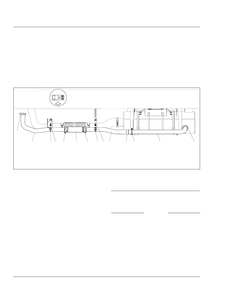
f490456
1
1
2
3
4
5
6
5
3
7
8
9
3
10
1.
Clamp
2.
Inlet Pipe
3.
U-Clamp
4.
Forward Pipe-Support Brace
5.
Slip Clamp
6.
CGI Bellows
7.
Center Pipe-Support Brace
8.
Center Pipe
9.
Clamp
10. Outlet Pipe
Fig. 8, CAT EPA07 Exhaust Installation with CGI Bellows
Exhaust
49
49/4