Content .. 1634 1635 1636 1637 ..
Ford F150 Pickup. Instruction - part 1636
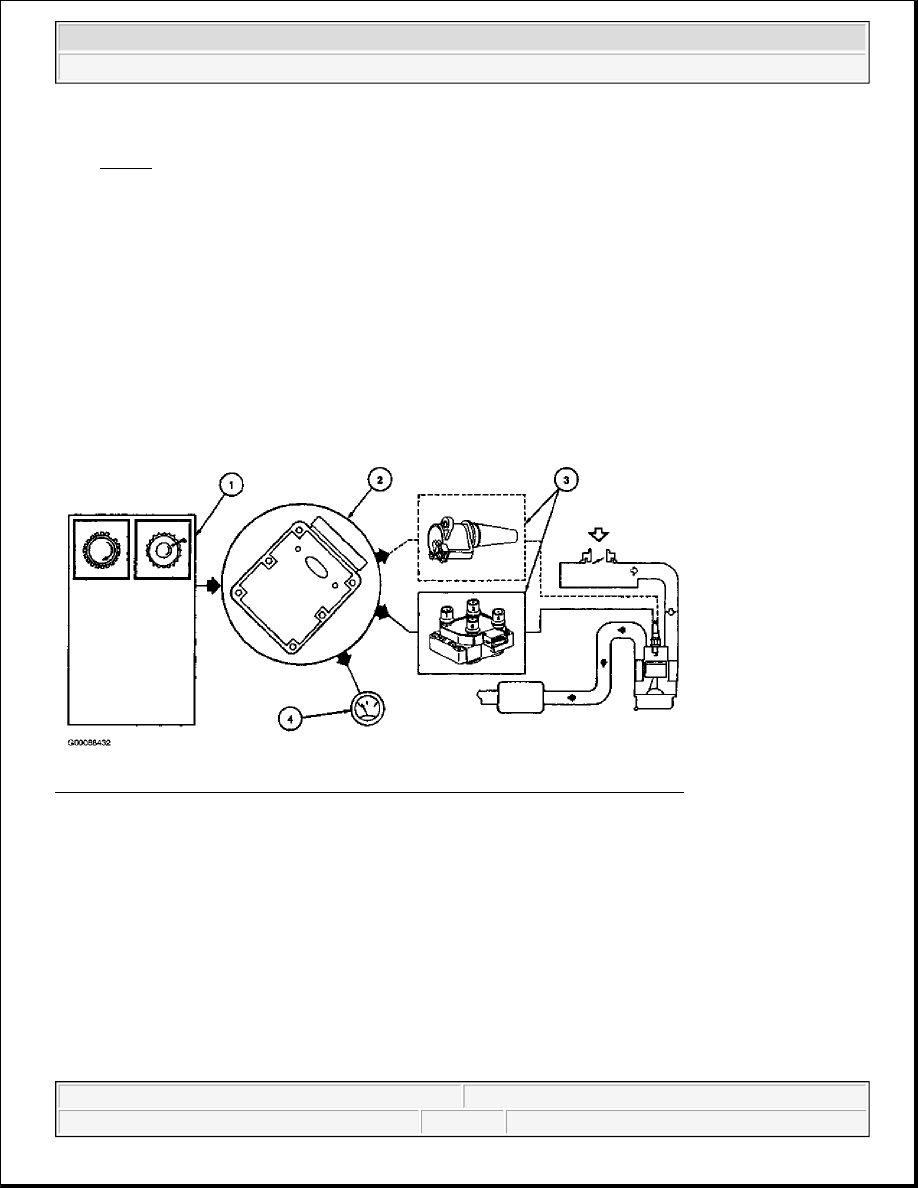
2. The PCM uses CKP signal to calculate a spark target and then fires coil pack(s) to that target shown. See
Fig. 50 . The PCM uses CMP sensor on COP Integrated EI Systems to identify top dead center of
compression of cylinder No. 1 to synchronize firing of individual coils.
3. The coils and coil packs receive their signal from PCM to fire at a calculated spark target. Each coil
within pack fires 2 spark plugs at the same time. The plugs are paired so that as one fires during
compression stroke, the other fires during exhaust stroke. The next time the coil is fired, the situation is
reversed. The COP system fires only one spark plug per coil and only on compression stroke. PCM acts
as an electronic switch to ground in the coil primary circuit. When the switch is closed, battery positive
voltage (B+) applied to coil primary circuit builds a magnetic field around primary coil. When the switch
opens, power is interrupted and primary field collapses inducing high voltage in secondary coil windings
and the spark plug is fired. A kickback voltage spike occurs when primary field collapses and the PCM
uses this voltage spike to generate an Ignition Diagnostic Monitor (IDM) signal. IDM communicates
information by pulse width modulation in PCM.
4. The PCM processes CKP signal and uses it to drive tachometer as Clean Tach Output (CTO) signal.
Fig. 49: Identifying Integrated Electronic Ignition System Components & Circuits
Courtesy of FORD MOTOR CO.
2003 Ford Pickup F150
2003 ENGINE PERFORMANCE Theory & Operation - CNG, Flex-Fuel & Gasoline