Ford F150 Pickup. Instruction - part 1376


  Index      Ford     Ford F150 Pickup - service and repair instruction 2003 year


Search            copyright infringement  


Content   ..  1374  1375  1376  1377   ..


Ford F150 Pickup. Instruction - part 1376


z

Operate the system and verify the concern is still present.  

Is the concern still present? If yes, install a new AFCM. If no, the system is operating correctly at this 
time. Concern may have been caused by a loose or corroded connector. 

TEST DA: FUEL RAIL TEMPERATURE 

Diagnostic Aids 

Enter this test only when all steps under QUICK TEST have been successfully completed and engine still does 
not start or if directed here from another test or chart. This test is only intended to diagnose:  

z

AFCM  

z

Circuitry  

z

FRT Sensor  

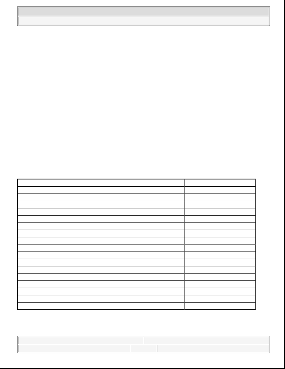
FRT SENSOR & RESISTANCE SPECIFICATIONS 

NOTE:

During bi-fuel diagnostics, intermittent failures are possible. Perform wiggle 
test and tap lightly on relays during testing. Ensure vehicle has CNG before 
continuing with diagnostics.

Temperature °F (°C)

K/Ohms

-40 (-40)

832.51

-4 (-20)

263.11

32 (0)

91.05

50 (10)

56.03

68 (20)

35.47

86 (30)

23.04

104 (40)

15.30

122 (50)

10.37

140 (60)

7.17

158 (70)

5.06

176 (80)

3.64

194 (90)

2.66

212 (100)

1.97

230 (110)

1.48

248 (120)

1.13

275 (135)

0.764

302 (150)

0.527


2003 Ford Pickup F150 

2003 ENGINE PERFORMANCE Self-Diagnostics - Bi-Fuel - Gasoline/CNG


Fig. 22: Identifying FRT Sensor Circuits 
Courtesy of FORD MOTOR CO. 

Testing 

1) Monitor The FRTMPAB PID 
 

z

Connect the scan tool.  

z

Key on, engine off.  

z

Access the AFCM.  

z

Select the FRTMPAB PID.  

z

See FRT SENSOR VOLTAGE & RESISTANCE SPECIFICATIONS table.  

Is the fuel rail temperature within the normal operating range? If yes, clear the DTCs. Road test the 
vehicle. Repeat the self-test. If DTC P0182 resets, go to next step. If DTC P0183 resets, go to step 4) . If 
no, for DTC P0182, go to next step. For DTC P0183, go to step 4) . 

2) Simulate An Opposite FRT Sensor Signal 
 

z

Key off.  

z

Disconnect the FRT sensor connector C1257.  

z

Key on, engine off.  

z

Monitor the FRTMPAB PID.  

Is the FRTMPAB PID less than -22 °F (-30°C)? If yes, install a new FRT sensor. If no, go to next step. 

3) Check The FRT Sensor Signal Circuit For A Short To Ground 
 

z

Key off.  

z

Disconnect the AFCM connector C1427.  

z

Measure the resistance between the FRT sensor connector C1257 signal circuit, harness side and 
ground. See Fig. 22 .  


2003 Ford Pickup F150 

2003 ENGINE PERFORMANCE Self-Diagnostics - Bi-Fuel - Gasoline/CNG


z

Measure the resistance between the FRT sensor connector C1257 signal circuit, harness side and 
the FRT sensor connector C1257 SIG RTN circuit, harness side.  

Are the resistances greater than 10,000 ohms? If yes, go to step 7) . If no, repair the circuit in question. 

4) Simulate An Opposite Sensor Signal 
 

z

Key off.  

z

Disconnect the FRT sensor connector C1257.  

z

Key on, engine off.  

z

Monitor the FRTMPAB PID.  

z

Connect a 5-amp fused jumper wire between the FRT sensor connector C1257 signal circuit, 
harness side and the FRT sensor connector C1257 SIG RTN circuit, harness side. See Fig. 22 .  

Is the FRTMPAB PID greater than 248°F (120°C)? If yes, install a new FRT sensor. If no, go to next 
step. 

5) Check The FRT Sensor Signal And SIG RTN Circuits For An Open 
 

z

Key off.  

z

Disconnect the AFCM connector C1427.  

z

Measure the resistance between the FRT sensor connector C1257 signal circuit, harness side and 
the AFCM connector C1427 terminal No. 31, harness side. See CONNECTOR 
IDENTIFICATION
 .  

z

Measure the resistance between the FRT sensor connector C1257 SIG RTN circuit, harness side 
and the AFCM connector C1427 terminal No. 89, harness side.  

Are the resistances less than 5 ohms? If yes, go to next step. If no, repair the circuit in question. 

6) Check The FRT Sensor Signal Circuit For A Short To Voltage 
 

z

Key on, engine off.  

z

Measure the voltage between the FRT sensor connector C1257 signal circuit, harness side and 
ground.  

Is any voltage indicated? If yes, repair the circuit. If no, go to next step. 

7) Check For Correct AFCM Operation 
 

z

Disconnect the AFCM.  

z

Check for corrosion and pushed out pins.  

z

Connect the AFCM connector and make sure it is seated correctly.  

z

Operate the system and verify the concern is still present. 


2003 Ford Pickup F150 

2003 ENGINE PERFORMANCE Self-Diagnostics - Bi-Fuel - Gasoline/CNG


Is the concern still present? If yes, install a new AFCM. If no, the system is operating correctly at this 
time. Concern may have been caused by a loose or corroded connector. 

TEST DE: FUEL RAIL PRESSURE SENSOR 

Diagnostic Aids 

Enter this test only when all steps under QUICK TEST have been successfully completed and engine still does 
not start or if directed here from another test or chart. This test is only intended to diagnose:  

z

AFCM  

z

Circuitry  

z

FRP Sensor  

Fig. 23: Identifying FRP Sensor Circuits 
Courtesy of FORD MOTOR CO. 

Testing 

1) Monitor The FRPREAB PID 
 

z

Connect the scan tool.  

z

Key on, engine off.  

z

Monitor the FRPREAB PID.  

Is the fuel rail pressure within 75 to 120 psi (517 to 827 kPa)? If yes, clear the DTCs. Road test the 
vehicle. Repeat the self-test. If DTC P0192 resets, go to next step. If DTC P0193 resets, go to step 5) . If 
no, for DTC P0192, go to next step. For DTC P0193, go to step 5) .

NOTE:

During bi-fuel diagnostics, intermittent failures are possible. Perform wiggle 
test and tap lightly on relays during testing. Ensure vehicle has CNG before 
continuing with diagnostics.


2003 Ford Pickup F150 

2003 ENGINE PERFORMANCE Self-Diagnostics - Bi-Fuel - Gasoline/CNG


Content   ..  1374  1375  1376  1377   ..