Ford Fiesta (1989-1995). Instruction - part 31
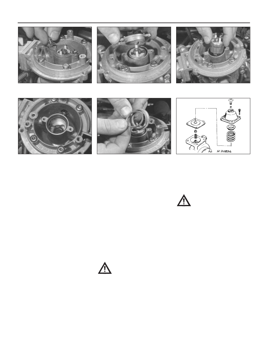
5 Bend over the locking tabs retaining the
injector screws, then undo and remove the
screws. Withdraw the injector retaining collar,
then carefully withdraw the injector from the
CFi unit (noting its orientation) followed by its
seals. Withdraw the seal from the retaining
collar (see illustrations).
6 Refit in the reverse order of removal.
Always use new seals in the CFi unit and the
retaining collar, and lightly lubricate them with
clean engine oil prior to assembly. Take care
not to damage the seals as they are fitted and
as the injector is fitted, check that the location
peg engages correctly.
Fuel pressure regulator
7 Refer to paragraphs 14 to 22 in this Section
and remove the CFi unit from the vehicle.
8 Unscrew and remove the four regulator
retaining screws, and remove the regulator
(see illustration). As they are removed, note
the fitting positions and the orientation of the
components. Do not (unless absolutely
necessary) attempt to prise out the plug or
adjust the screw in the centre of the housing
(if no plug is fitted), as this will alter the system
pressure.
9 Examine the components, and renew any
that are defective or suspect.
10 To refit, position the regulator on its side,
then insert the small spring, the valve,
diaphragm (ensuring that it seats correctly),
large spring, cup and then the regulator cover.
Insert and tighten the retaining screws, but
take care not overtighten them, or the cover
will be distorted.
11 Carefully place the ball into position on
the spring cup, and ensure that it seats
correctly.
12 If removed, fit the central Allen type
adjuster screw, hand-tighten it and then
unscrew it (from the hand-tight position) three
full turns to make a provisional adjustment.
13 Refit the CFi unit in accordance with
paragraphs 23 to 25 in this Section, but note
that further checks for fuel leaks must be
made with the engine running. The fuel
system pressure must be checked by a Ford
dealer or other suitable specialist at the
earliest opportunity.
CFi unit
14 Relieve the residual pressure in the fuel
system (see Section 2), and equalise tank
pressure by removing the fuel filler cap.
Warning: This procedure will
merely relieve the increased
pressure necessary for the
engine to run - remember that
fuel will still be present in the system
components, and take precautions
accordingly before disconnecting any of
them.
15 Disconnect the battery negative (earth)
lead (refer to Chapter 5A, Section 1).
16 Refer to Section 4 and remove the air
cleaner.
17 Position a suitable drain tray under the
coolant hose connections to the CFi unit.
Ensure that the cooling system is not
pressurised (see Chapter 1), then detach the
hoses from the unit. Plug or clamp the hoses
to prevent further coolant spillage whilst the
hoses are detached.
Warning: DO NOT attempt to
remove the expansion tank filler
cap, or to disturb any part of the
cooling system, while it or the
engine is hot, as there is a very great risk
of scalding. If the expansion tank filler cap
must be removed before the engine and
radiator have fully cooled down (even
though this is not recommended) the
pressure in the cooling system must first
be released. Cover the cap with a thick
layer of cloth, to avoid scalding, and slowly
unscrew the filler cap until a hissing sound
can be heard. When the hissing has
stopped, showing that pressure is
released, slowly unscrew the filler cap
further until it can be removed; if more
hissing sounds are heard, wait until they
have stopped before unscrewing the cap
completely. At all times, keep well away
from the filler opening.
18 Disconnect the fuel return pipe from the
CFi unit.
19 Refer to Section 5 and disconnect the
accelerator cable from the CFi unit.
20 Disconnect the inlet air temperature
sensor, throttle plate control motor and
throttle position sensor wiring multi-plug
connectors.
4B•6 Fuel system - central fuel injection engines
14.8 Exploded view of the fuel pressure
regulator assembly
14.5e Withdrawing the seal from the
injector retaining collar
14.5d Injector seals in the CFi unit
14.5c Withdrawing the injector from the
CFi unit
14.5b Removing the injector retaining
collar
14.5a Removing an injector retaining
collar securing bolt and its locktab
1595Ford Fiesta Remake