Dodge Viper SRT-10 (ZB). Manual - part 240


  Index      Dodge     Dodge Viper SRT-10 (ZB) - service repair manual 2005 year


Search            


Content   ..  238  239  240  241   ..


Dodge Viper SRT-10 (ZB). Manual - part 240


FRONT FENDER

REMOVAL

Fender

(1) Remove the sill panel. (Refer to 23 - BODY/EX-

TERIOR/SILL PANEL - REMOVAL)

(2) Remove the three screws and remove the door

hinge cover. (Fig. 27)

(3) Remove the screws attaching the fender grille

to the fender and the sill.

(4) Remove the front wheelhouse splash shield.

(Refer to 23 - BODY/EXTERIOR/FRONT WHEEL-
HOUSE SPLASH SHIELD - REMOVAL)

(5) Remove the screws attaching the fender to the

fascia. (Fig. 28)

(6) Remove the rivets attaching the fender to the

support bracket.

(7) Remove the nuts where the hinge cover is

attached.

(8) Remove the rear screws.
(9) Remove the upper bolts and remove the fender.

(Fig. 29)

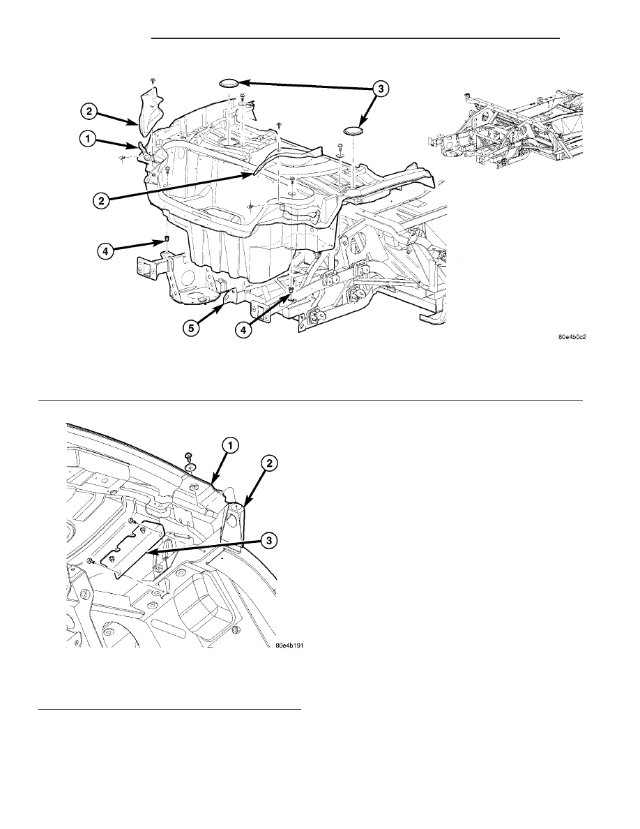
Fig. 25 TRUNK PAN ASSEMBLY

1 - TRUNK PAN ASSEMBLY
2 - TAIL LAMP COVER PANEL (RIGHT/LEFT)
3 - SHOCK SERVICE PLUG

4 - FRAME RAIL NUT/RIVET
5 - FRAME ASSEMBLY

Fig. 26 TRUNK PAN REAR BRACKET

1 - TRUNK PAN ASSEMBLY
2 - FRAME ASSEMBLY
3 - TRUNK PAN TO FRAME ATTACHING REAR BRACKET

23 - 52

EXTERIOR

ZB

TRUNK PAN (Continued)

Fender Support

(1) Remove the bolts attaching the support to the

frame. (Fig. 30)

(2) Remove the nut attaching the support to the

front of dash panel.

Fig. 27 DOOR HINGE COVER

1 - U-NUTS (3 PER SIDE)
2 - U-NUTS (2 PER SIDE)
3 - SCREW (1 PER SIDE)
4 - FENDER GRILLE
5 - SCREWS (3 PER SIDE)
6 - HINGE COVER

Fig. 28 FRONT FENDER

1 - RIVETS
2 - FENDER SUPPORT
3 - WINDSHIELD SURROUND
4 - BOLTS
5 - SCREWS

6 - FENDER
7 - NUTS
8 - U-NUTS
9 - SILL/FENDER BRACKET

Fig. 29 FENDER PANEL

1 - NUTS
2 - BOLTS (8)
3 - FENDER
4 - SCREWS
5 - WINDSHIELD SURROUND

ZB

EXTERIOR

23 - 53

FRONT FENDER (Continued)

(3) Using a heat gun, heat attachment area to at

least 121°C (250°F) to soften adhesive attaching
fender support to frame.

(4) Using a flat blade scraper, cut adhesive from

between fender support and frame.

(5) Remove the fender support.

INSTALLATION

Fender Support

CAUTION: Clean only the area of the frame where
the old adhesive is present or corrosion resistance
may be compromised.

(1) Using a 3M

t Purple Scotch-Brite™ Clean &

Strip XT Disc or equivalent, clean adhesive residue
from frame.

NOTE: Do not apply adhesive close to the inboard
edge of the fender support when installed. Avoid
unsightly “squeeze out”.

(2) Using a structural adhesive suitable for bond-

ing carbon fiber to steel, apply adhesive bead 10 - 15
mm (3/8 in. to 5/8 in.) to the bonding surfaces on
frame from front to rear in the locations indicated.
(Fig. 31)

NOTE: Adhesive will begin to harden in approxi-
mately 3

1

2

minutes of first application.

(3) Install the fender support and align with

marks made previously.

(4) Install and tighten the nut to 17 N·m (13 ft.

lbs.).

(5) Install the center screw and tighten to 17 N·m

(13 ft. lbs.).

(6) Install the front screw and tighten to 17 N·m

(13 ft. lbs.).

(7) Check for air gaps in adhesive.

Fender

(1) Install the fender and loosely install the fasten-

ers.

(2) Tighten the upper bolts to 5 N·m (45 in. lbs.)

using the sequence shown. (Fig. 32)

(3) Install new rivets securing the fender to the

support bracket.

(4) Tighten

the

fender

to

headlamp

support

screws.

(5) Tighten the screw securing the fender to the

cowl.

(6) Tighten the nuts attaching the fender to the

front of dash panel to 5 N·m (45 in. lbs.).

(7) Tighten the rear fender to sill bolt to 5 N·m (45

in. lbs.).

(8) Tighten the rear fender screw.
(9) Install the fender grille and install the upper

screw attaching the grille to the fender.

(10) Install the lower grille screw at the sill.
(11) Install the door hinge cover and install the

three screws to the fender.

Fig. 30 FENDER INNER SUPPORT ASSEMBLY

1 - FENDER INNER SUPPORT ASSEMBLY
2 - SPRING NUT
3 - FRONT OF DASH PANEL

4 - WINDSHIELD SURROUND COMPLETE FRAME
5 - FRAME ASSEMBLY

23 - 54

EXTERIOR

ZB

FRONT FENDER (Continued)

FRONT FENDER - EXPORT

REMOVAL

Fender

(1) Remove the sill panel (Refer to 23 - BODY/EX-

TERIOR/ROCKER PANEL COVER - REMOVAL).

(2) Remove the front wheelhouse splash shield

(Refer to 23 - BODY/EXTERIOR/FRONT WHEEL-
HOUSE SPLASH SHIELD - REMOVAL).

(3) Remove the screws attaching the fender to the

fascia. (Fig. 33)

(4) Remove the rivets attaching the fender to the

support bracket.

(5) Remove the nuts where the hinge cover is

attached.

(6) Remove the rear screws.
(7) Remove the upper bolts and remove the fender

(Fig. 34).

Fender Support

(1) Remove the bolts attaching the support to the

frame (Fig. 35).

Fig. 31 ADHESIVE LOCATIONS

1 - SEALER LOCATIONS - FRAME
2 - SEALER LOCATIONS - FRAME/FRONT OF DASH PANEL

3 - FRONT OF DASH PANEL
4 - FRAME

Fig. 32 FENDER TIGHTENING SEQUENCE

ZB

EXTERIOR

23 - 55

FRONT FENDER (Continued)


Content   ..  238  239  240  241   ..