Dodge Viper SRT-10 (ZB). Manual - part 47


  Index      Dodge     Dodge Viper SRT-10 (ZB) - service repair manual 2005 year


Search            


Content   ..  45  46  47  48   ..


Dodge Viper SRT-10 (ZB). Manual - part 47


CLUTCH DISC

REMOVAL

(1) Remove transmission.
(2) Remove clutch inspection cover 2 screws.
(3) Remove bell housing bolts (6). Remove bell

housing from engine (Fig. 7).

(4) Mark clutch cover (pressure plate) and flywheel

to maintain their same relative positions when rein-
stalling clutch assembly.

(5) Insert Clutch Disc Aligning Tool through the

clutch disc hub to prevent the clutch disc from falling
and damaging the facings.

(6) Loosen clutch cover (pressure plate) attaching

bolts, one or two turns at a time, in a crisscross pat-
tern. This will release spring pressure evenly and
avoid clutch cover damage.

(7) Remove

the

clutch

cover

(pressure

plate)

assembly and disc from flywheel. Handle carefully to
avoid contaminating the friction surfaces.

CLEANING

Clean flywheel face with crocus cloth or 400-600

grade sandpaper, then wipe the surface with mineral
spirits. If the surface is severely scored, heat checked
or warped, replace the flywheel.

CAUTION: Never machine the flywheel face. If fly-
wheel surface is bad the flywheel must be replaced.

Wipe the friction surface of the pressure plate with

mineral spirits.

INSTALLATION

NOTE: If the flywheel is to be replaced or removed
apply thread sealer to the flywheel retaining bolts
when installing. This will prevent engine oil from
leaking onto the clutch.

(1) Mount clutch assembly on flywheel (Fig. 8),

being careful to properly align dowels and the align-
ment marks made before removal. If new clutch or
flywheel is installed, align cover balance spot as close
as possible to flywheel balance orange spot. Apply
pressure to the alignment tool. Lightly tighten the
clutch cover bolts enough to hold the disc in position.

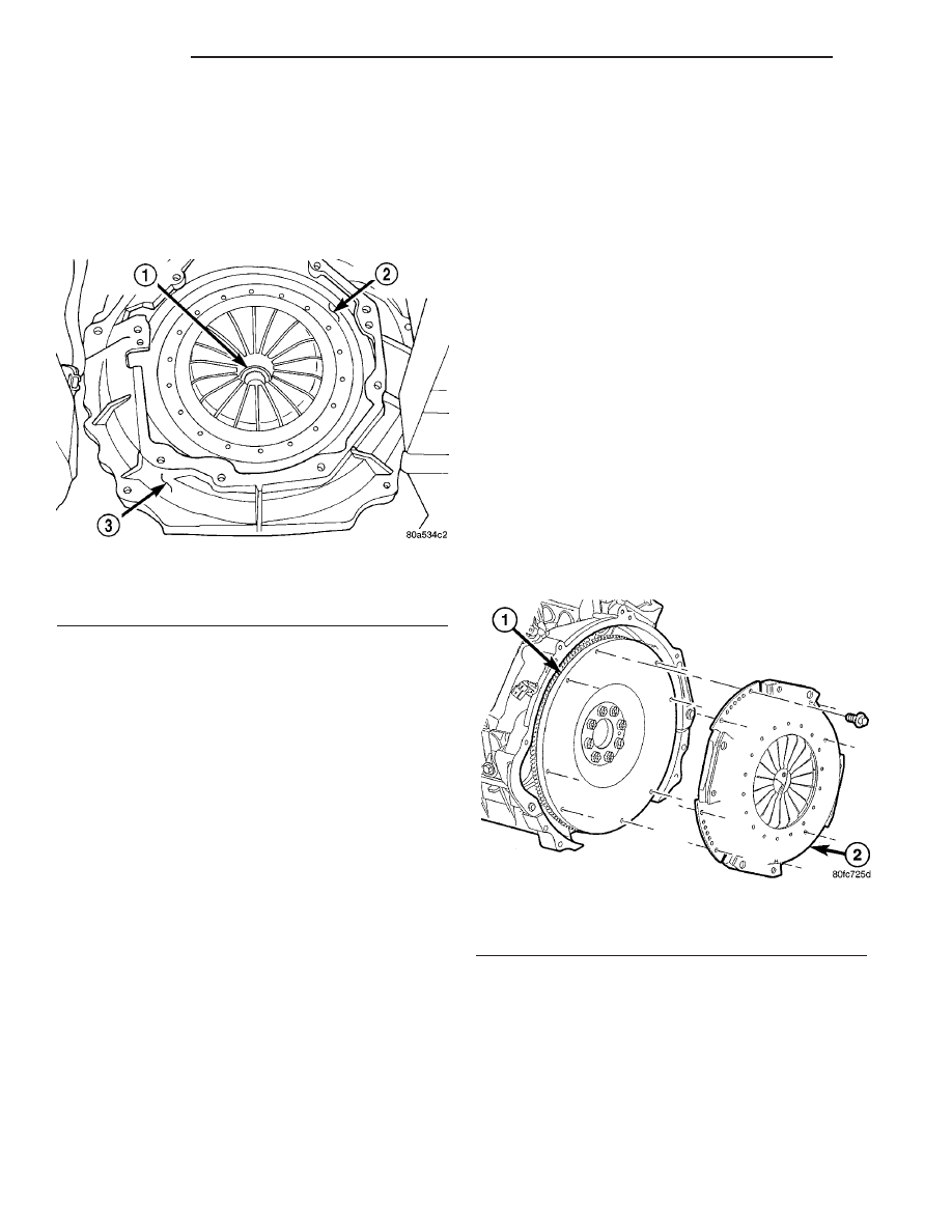
Fig. 7 CLUTCH BELLHOUSING

1 - CLUTCH DISC
2 - PRESSURE PLATE
3 - BELL HOUSING

Fig. 8 CLUTCH ASSEMBLY

1 - FLYWHEEL
2 - PRESSURE PLATE

6 - 8

CLUTCH

ZB

(2) To avoid distortion of the clutch cover (pressure

plate), tighten bolts a few turns at a time in
sequence (Fig. 9) until bolts are seated. Then tighten
bolts in sequence to 30 N·m (270 in. lbs.). Remove
clutch disc alignment tool.

(3) Install transmission into vehicle.

CLUTCH RELEASE BEARING

REMOVAL

NOTE: The bearing and slave cylinder are serviced
together as an assembly. Do not attempt to sepa-
rate the bearing from the slave cylinder.

(1) Raise vehicle on hoist.
(2) Disconnect hydraulic line from hydraulic slave

cylinder. Use the quick disconnect tool (special tool
6638) to open the coupling.

(3) Remove transmission assembly from the vehi-

cle.

(4) Remove slave cylinder (Fig. 10) from transmis-

sion.

INSTALLATION

(1) Install slave cylinder onto transmission.
(2) Install transmission assembly into the vehicle.
(3) Connect hydraulic line fto slave cylinder.
(4) Bleed the system.

FLYWHEEL

DIAGNOSIS AND TESTING

Common causes of flywheel problems:
• Incorrect bolt tightening

• Mounting the flywheel on a dirty crankshaft

flange

• Improper seating on the crankshaft flange shoul-

der

• Heat warpage

• Loose flywheel to crankshaft bolts
The flywheel should be replaced if warped or over-

heated. Do not machine the face of the flywheel
to correct a warped or overheated condition.

Clean the crankshaft flange and its mating surface

on the flywheel before assembling. dirt/grease in this
area could cause the flywheel to mis-align when
installing.

Use new bolts when mounting flywheel and secure

the bolts with Mopar Lock and Seal or equivalent.
Tighten flywheel bolts to specified torque only. Over
tightening can distort the flywheel causing run out.

Fig. 9 TORQUE SEQUENCE

Fig. 10 Release Bearing/Hydraulic Slave Cylinder

1 - HYDRAULIC CLUTCH RELEASE
2 - BLEED SCREW
3 - TRANSMISSION

ZB

CLUTCH

6 - 9

CLUTCH DISC (Continued)

LINKAGE

DESCRIPTION

The hydraulic linkage consists of a clutch master

cylinder, reservoir, a clutch slave cylinder/release
bearing assembly and an interconnecting fluid line.

The clutch master cylinder push rod is connected

to the clutch pedal. The slave cylinder/release bear-
ing is mounted to the transmission front cover. The
clutch master cylinder is mounted on the driver side
of the dash panel adjacent to the brake master cylin-
der and booster assembly.

OPERATION

The clutch linkage uses hydraulic pressure to oper-

ate the clutch. Depressing the clutch pedal develops
fluid pressure in the clutch master cylinder. This
pressure is transmitted to the slave cylinder through
a connecting line. In turn, the slave cylinder forces
the release bearing into the pressure plate dia-
phragm spring. As additional force is applied, the
bearing presses the diaphragm spring fingers inward
on the fulcrums. This action moves the pressure
plate rearward relieving clamp force on the disc.

The slave cylinder/release bearing assembly has an

integral spring which preloads the release bearing
against the clutch diaphragm fingers to maintain
zero free-play.

MASTER CYLINDER

REMOVAL

(1) Remove master cylinder actuation rod to clutch

pedal clip.

(2) Remove anti-rotation pin from the toe box and

discard pin.

NOTE: Anti-rotation pin must not be reused.

(3) Disconnect clutch pedal position switch connector.
(4) Remove mounting screws on clutch fluid reser-

voir.

(5) Disconnect

hydraulic

line

quick

connector

located at clutch bell housing. Use special tool 6638
to separate quick connector.

CAUTION: Do not allow brake fluid to come in con-
tact with painted surfaces of the vehicle. Paint dam-
age may occur.

(6) Remove left inner fender for access to the mas-

ter cylinder.

(7) Twist clutch master cylinder a quarter turn

counterclockwise to remove from toe box.

(8) Remove assembly from vehicle.

INSTALLATION

(1) Twist clutch master cylinder a quarter turn

clockwise to install into toe box.

(2) Connect hydraulic line quick connector to

clutch bell housing.

(3) Install clutch fluid reservoir mounting screws.
(4) Install left inner fender.
(5) Connect clutch pedal position switch connector.
(6) Install new anti-rotation pin.
(7) Install master cylinder actuation rod to clutch

pedal clip.

(8) Bleed system.

CLUTCH PEDAL POSITION
SWITCH

DESCRIPTION

The clutch pedal position switch is located on the

clutch master cylinder actuation rod (Fig. 11). The
switch is held in place by a plastic retaining clip. The
clutch master cylinder must be removed to replace
this switch.

OPERATION

The function of the clutch pedal position switch is

to prevent the engine starter from operating until the
clutch pedal is depressed. This switch will prevent
accidental engagement of starter while vehicle is in
gear.

Fig. 11 CLUTCH SWITCH LOCATION

1 - CLUTCH POSITION SWITCH CONNECTOR
2 - HYDRAULIC CLUTCH MASTER CYLINDER
3 - CLUTCH POSITION SWITCH
4 - CLUTCH ACTUATION ROD

6 - 10

CLUTCH

ZB

WARNING: UNDER NO CIRCUMSTANCES SHOULD
THE

CLUTCH

POSITION

SWITCH

BE

DISCON-

NECTED OR DISABLED.

There is no adjustment on the clutch position

switch. If the switch is not operating correctly, it
must be replaced as an assembly.

DIAGNOSIS AND TESTING

(1) Disconnect the connector on the clutch position

switch from the vehicle wiring harness.

(2) Place a ohmmeter across the terminals of the

switch connector. The switch should show no continu-
ity with the clutch pedal in the released (clutch
engaged) position.

(3) Slowly push the clutch pedal to the floor

(clutch disengaged). The ohmmeter should show con-
tinuity just before the pedal reaches the end of its
travel.

(4) If the clutch switch shows continuity with

clutch pedal up or no continuity with clutch pedal
down, the switch is defective. The switch has no ser-
viceable parts and should be replaced as an assem-
bly.

REMOVAL

(1) Disconnect the clutch pedal position switch

connector.

(2) Disconnect the clutch actuation rod from the

clutch pedal.

(3) Remove the clutch master cylinder from the toe

box.

(4) Remove the white clutch pedal position switch

retaining clip (Fig. 12).

(5) Push the switch up the rod slightly. Then pull

the bottom of the switch outward (Fig. 13).

Fig. 12 SWITCH RETAINER CLIP

1 - RETAINING CLIP

Fig. 13 SWITCH REMOVAL

1 - CLUTCH SWITCH
2 - CLUTCH ACTUATION ROD
3 - CLUTCH MASTER CYLINDER

ZB

CLUTCH

6 - 11

CLUTCH PEDAL POSITION SWITCH (Continued)


Content   ..  45  46  47  48   ..