Dodge Sprinter. Manual - part 280


  Index      Dodge     Dodge Sprinter / Mercedes-Benz - service repair manual 2006 year


Search            


Content   ..  278  279  280  281   ..


Dodge Sprinter. Manual - part 280


INPUT CLUTCHES

DESCRIPTION

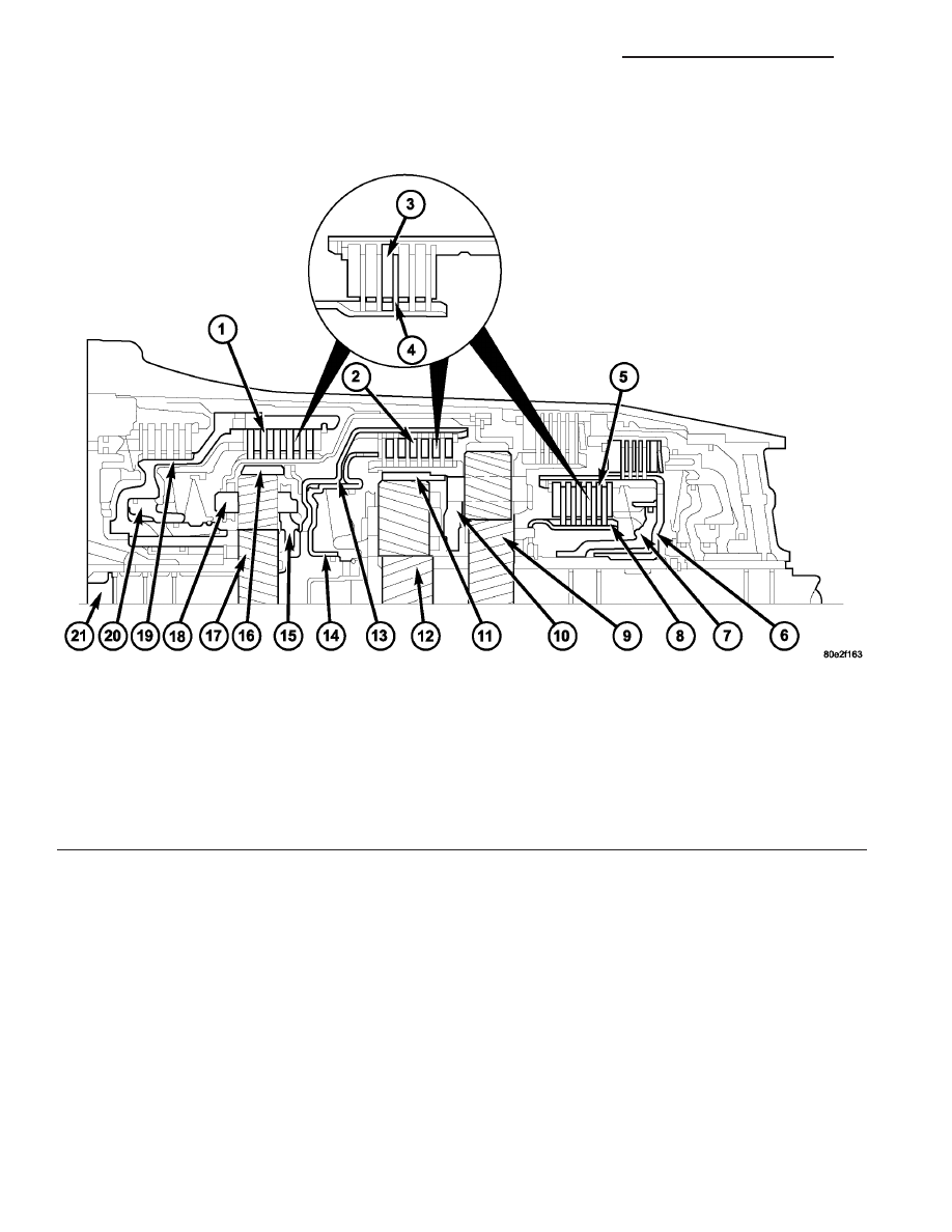
Three multi-plate input clutches (1, 2, 5) (Fig. 79),

the front, middle and rear multi-plate clutches K1
(1), K2 (2), and K3 (5), are located in the planetary
gear sets in the transmission housing.

A multi-plate input clutch consists of a number of

internally toothed discs (4) on an internally toothed
disc carrier and externally toothed discs (3) on an
externally toothed disc carrier.

Fig. 79 Input Clutches

1 - K1 CLUTCH

12 - CENTER PLANETARY GEARSET SUN GEAR

2 - K2 CLUTCH

13 - K2 CLUTCH EXTERNALLY TOOTHED DISC CARRIER

3 - EXTERNALLY TOOTHED DISC

14 - K2 CLUTCH PISTON

4 - INTERNALLY TOOTHED DISC

15 - FRONT PLANETARY GEARSET PLANETARY CARRIER

5 - K3 CLUTCH

16 - FRONT PLANETARY GEARSET ANNULUS GEAR

6 - K3 CLUTCH EXTERNALLY TOOTHED DISC CARRIER

17 - FRONT PLANETARY GEARSET SUN GEAR

7 - K3 CLUTCH PISTON

18 - K1 CLUTCH INTERNALLY TOOTHED DISC CARRIER

8 - K3 CLUTCH INTERNALLY TOOTHED DISC CARRIER

19 - K1 CLUTCH EXTERNALLY TOOTHED DISC CARRIER

9 - REAR PLANETARY GEARSET SUN GEAR

20 - K1 CLUTCH PISTON

10 - CENTER PLANETARY GEARSET PLANETARY CARRIER

21 - DRIVE SHAFT

11 - CENTER PLANETARY GEARSET ANNULUS GEAR

21 - 90

AUTOMATIC TRANSMISSION NAG1 - SERVICE INFORMATION

VA

OPERATION

The input clutches (Fig. 80) produce a non-positive

locking connection between two elements of a plane-
tary gear set or between one element from each of
two planetary gear sets in order to transmit the drive
torque.

If the piston (20) on multi-plate clutch K1 (1) is

subjected to oil pressure, it presses the internal and
external discs of the disc set together. The sun gear
(17) is locked with the planetary carrier (15) via the
externally toothed disc carrier (19) and the internally
toothed disc carrier (18). The front planetary gear set
is thus locked and turns as a closed unit.

If the multi-plate clutch K2 (2) is actuated via the

piston (14), the piston compresses the disc set. The
annulus gear (16) of the front planetary gear set is
locked with the annulus gear (11) of the center plan-
etary gear set via the externally toothed disc carrier

(13) and the center planetary carrier (10) on which
the internally toothed discs are seated. Annulus gear
(16) and annulus gear (11) turn at the same speed as
the input shaft (21)

If the multi-plate clutch K3 (5) is actuated via the

piston (7), the piston compresses the disc set. The
sun gear (12) of the center planetary gear set is
locked with the sun gear (9) of the rear planetary
gear set via the externally toothed disc carrier (6)
and the internally toothed disc carrier (8). Sun gear
(12) and sun gear (9) turn at the same speed.

Fig. 80 Input Clutches

1 - K1 CLUTCH

12 - CENTER PLANETARY GEARSET SUN GEAR

2 - K2 CLUTCH

13 - K2 CLUTCH EXTERNALLY TOOTHED DISC CARRIER

3 - EXTERNALLY TOOTHED DISC

14 - K2 CLUTCH PISTON

4 - INTERNALLY TOOTHED DISC

15 - FRONT PLANETARY GEARSET PLANETARY CARRIER

5 - K3 CLUTCH

16 - FRONT PLANETARY GEARSET ANNULUS GEAR

6 - K3 CLUTCH EXTERNALLY TOOTHED DISC CARRIER

17 - FRONT PLANETARY GEARSET SUN GEAR

7 - K3 CLUTCH PISTON

18 - K1 CLUTCH INTERNALLY TOOTHED DISC CARRIER

8 - K3 CLUTCH INTERNALLY TOOTHED DISC CARRIER

19 - K1 CLUTCH EXTERNALLY TOOTHED DISC CARRIER

9 - REAR PLANETARY GEARSET SUN GEAR

20 - K1 CLUTCH PISTON

10 - CENTER PLANETARY GEARSET PLANETARY CARRIER

21 - DRIVE SHAFT

11 - CENTER PLANETARY GEARSET ANNULUS GEAR

VA

AUTOMATIC TRANSMISSION NAG1 - SERVICE INFORMATION

21 - 91

INPUT CLUTCH K1

DISASSEMBLY

(1) Remove snap-ring (11) (Fig. 81) from outer

multiple-disc carrier (6).

(2) Take multiple-disc pack (12) out of outer mul-

tiple-disc carrier (6). Note which clutch disc is
removed just prior to the spring plate (8) for re-as-
sembly. If the clutch discs are re-used, this disc must
be returned to its original position on top of the
spring plate.

Fig. 81 Input Clutch K1 Components

1 - K1 OUTER DISC CARRIER

7 - DISC SPRING

2 - FREEWHEELING CLUTCH F1

8 - SPRING PLATE

3 - SNAP-RING

9 - SPRING PLATE SEALING RING

4 - OUTER DISC CARRIER SEALING RING

10 - SNAP-RING

5 - PISTON SEALING RING

11 - SNAP-RING

6 - PISTON

12 - MULTIPLE DISC PACK - REFER TO TEXT FOR CORRECT
ASSEMBLY ORDER

21 - 92

AUTOMATIC TRANSMISSION NAG1 - SERVICE INFORMATION

VA

(3) Place Multi-use Spring Compressor 8900 (2)

(Fig. 82) on the spring plate and compress the spring
until the snap-ring (1) is exposed.

(4) Remove snap-ring (1).
(5) Take out disc spring (7) and remove piston (6)

by carefully blowing compressed air into the drilled
oil feed passage.

(6) Remove snap-ring (3) and take out front free-

wheeling clutch F1 (2). Take care when removing the
F1 clutch to prevent the clutch sprags from falling
out. If this occurs, the clutch must be replaced.

Fig. 82 Compress the Disc Spring

1 - SNAP-RING
2 - MULTI-USE SPRING COMPRESSOR 8900

VA

AUTOMATIC TRANSMISSION NAG1 - SERVICE INFORMATION

21 - 93


Content   ..  278  279  280  281   ..