Dodge Caliber. Manual - part 510
3.
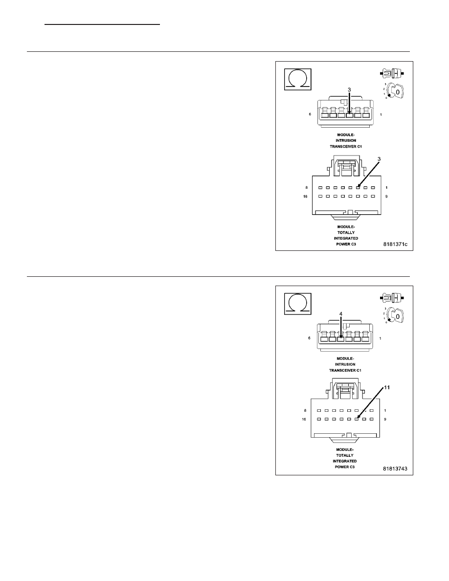
(D55) CAN B BUS (+) CIRCUIT OPEN
Turn the ignition off.
Disconnect the negative battery cable.
Disconnect the Intrusion Transceiver Module connector.
Disconnect the TIPM C3 connector.
Measure the resistance of the (D55) CAN B Bus (+) circuit between the
TIPM C3 connector and the Intrusion Transceiver Module connector.
Is the resistance below 2.0 ohms?
Yes
>> Go To 4
No
>> Repair the (D55) CAN B Bus (+) circuit for an open.
Perform BODY VERIFICATION TEST - VER 1. (Refer to 8 -
ELECTRICAL/ELECTRONIC
CONTROL
MODULES
-
STANDARD PROCEDURE)
4.
(D54) CAN B BUS (–) CIRCUIT OPEN
Measure the resistance of the (D54) CAN B Bus (–) circuit between the
TIPM C3 connector and the Intrusion Transceiver Module connector.
Is the resistance below 2.0 ohms?
Yes
>> Replace the Intrusion Transceiver Module in accordance
with the Service Information.
Perform BODY VERIFICATION TEST - VER 1. (Refer to 8 -
ELECTRICAL/ELECTRONIC
CONTROL
MODULES
-
STANDARD PROCEDURE)
No
>> Repair the (D54) CAN B Bus (–) circuit for an open.
Perform BODY VERIFICATION TEST - VER 1. (Refer to 8 -
ELECTRICAL/ELECTRONIC
CONTROL
MODULES
-
STANDARD PROCEDURE)
U0141-LOST COMMUNICATION WITH FRONT CONTROL MODULE (TIPM)
For a complete wiring diagram Refer to Section 8W.
PM
VEHICLE THEFT SECURITY - ELECTRICAL DIAGNOSTICS
8Q - 17