Dodge Caliber. Manual - part 1308


  Index      Dodge     Dodge Caliber - service repair manual 2007 year


Search            


Content   ..  1306  1307  1308  1309   ..


Dodge Caliber. Manual - part 1308


If the new high spot is NOT within 102 mm (4.0 inch) of either high spot, draw an arrow on the tread from new
high spot toward the original (2). Break down the
tire and remount it 90 degrees on rim in that
direction, then re-measure runout. This will nor-
mally

reduce

the

runout

to

an

acceptable

amount.

6. Once back together, road test the vehicle for at least 5 miles, following the format described in Road Test. If

vibration persists, and all components tested are within specification, the tires may have an excessive radial
force condition. Radial force variation can be checked using a wheel balancer capable of measuring radial force
variation, such as the Hunter GSP 9700 Vibration Control System (Wheel Balancer) or equivalent. If this equip-
ment is not available, consult with the tire manufacturer.

STANDARD PROCEDURE

TIRE AND WHEEL BALANCE

NOTE: Balance equipment must be calibrated and maintained per equipment manufacturer’s specifications.

Wheel balancing can be accomplished with either on-vehicle or off-vehicle equipment.

NOTE: If using on-vehicle balancing equipment, on the driving axle, remove the opposite wheel and tire
assembly.

It is recommended that a two-plane dynamic balancer be used when a tire and wheel assembly requires balancing.
A static balancer should only be used when a two-plane balancer is not available.

Balance wheel and tire assemblies dynamically and statically to less than 0.25 (

1

4

) ounce.

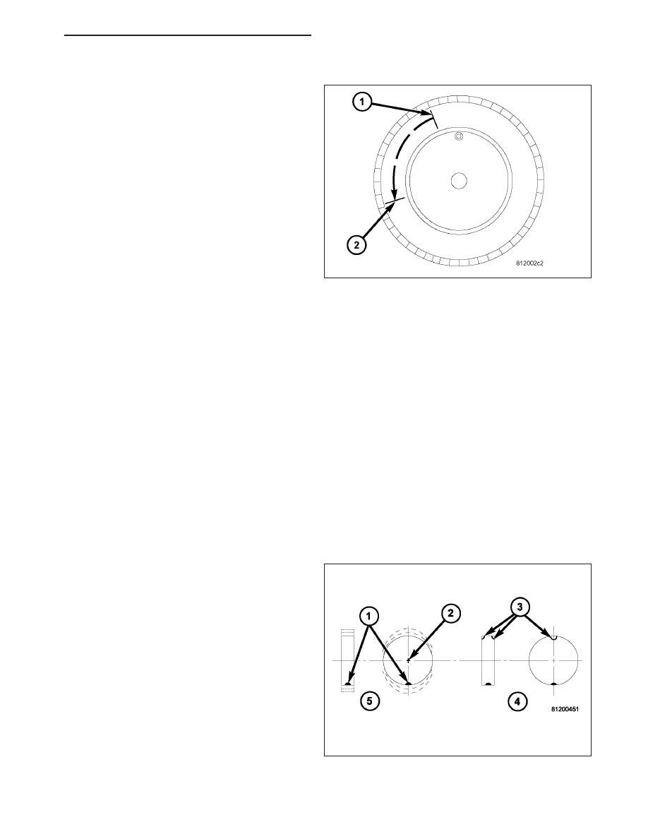
For static balancing, find the location of the heavy
spot causing the imbalance (1). Counter balance the
wheel directly opposite the heavy spot. Determine
weight required to counterbalance the area of imbal-
ance. Place half of this weight on the inner rim flange
and the other half on the outer rim flange (3) at the
predetermined spots.

PM

TIRES/WHEELS - SERVICE INFORMATION

22 - 59

For dynamic balancing, the balance equipment is
designed to indicate the location and amount of weight
to be applied to both the inner and outer rim flanges
(2).

The aluminum wheels on this vehicle use a different wheel weight than do the steel wheels. Be sure to use the
correct wheel weight for the wheel type.

Always verify the Balance. When using off-vehicle equipment, remount the tire and wheel assembly 180 degrees on
the balancer spindle and recheck balance. Balance variation from one spot to the other should not be more than
0.125 (

1

8

) ounce. If variation is more than 0.125 ounce, balancing equipment could be malfunctioning.

If difficult to balance, break down the tire and wheel assembly and check for loose debris inside the tire. Prior to
disassembly, mark (index) the tire at the valve stem. Use this mark in order to remount the tire in its original ori-
entation with respect to the wheel.

TIRE AND WHEEL MATCH MOUNTING

Wheels and tires are match mounted at the factory. This means that the high spot of the tire is matched to the low
spot on the wheel rim. This technique is used to reduce runout in the wheel and tire assembly. The high spot on the
tire is marked with a paint mark or a bright colored adhesive label on the outboard sidewall. The low spot on the
wheel is identified with a label on the outside of the rim and a dot or line in the drop well area of the rim (inside
where the tire mounts). If the outside label has been removed, the tire will have to be removed to locate the dot or
line on the inside of the rim. The tire can then be match mounted to the tire.

Information on match mounting the tire to the wheel can be found in Tire and Wheel Runout/Match Mounting, items
(2) through (5), within Diagnosis And Testing - Tire And Wheel Vibration. (Refer to 22 - TIRES/WHEELS - DIAG-
NOSIS AND TESTING)

TIRE AND WHEEL ROTATION

NOTE: Refer to the Owner’s Manual for rotation schedules.

22 - 60

TIRES/WHEELS - SERVICE INFORMATION

PM

NON-DIRECTIONAL TREAD PATTERN TIRES

Tires on the front and rear operate at different loads
and perform different steering, driving, and braking
functions. For these reasons they wear at unequal
rates and tend to develop irregular wear patterns.
These effects can be reduced by rotating the tires at
regular intervals. The benefits of tire rotation are:

Increase tread life

Maintain traction levels

A smooth, quiet ride

The suggested method of tire rotation is shown in this
graphic. Other rotation methods can be used, but they
will not provide all the tire longevity benefits.

NOTE: Only the 4 tire rotation method may be
used if the vehicle is equipped with a compact or
temporary spare tire.

DIRECTIONAL TREAD PATTERN TIRES

Some vehicles may be fitted with special high-performance tires having a directional tread pattern. These tires are
designed to improve traction on wet pavement. To obtain the full benefits of this design, the tires must be installed
so that they rotate in the correct direction. This is indicated by arrows on the tire sidewalls.

When being installed, extra care is needed to ensure that this direction of rotation is maintained.

REMOVAL

TIRE AND WHEEL ASSEMBLY - ALUMINUM WHEEL

1. Raise and support the vehicle so that tire and wheel assembly clears ground level. (Refer to LUBRICATION &

MAINTENANCE/HOISTING - STANDARD PROCEDURE)

2. If the vehicle is equipped with wheel center caps that cover the wheel nuts, remove the cap with an appropriate

removal tool utilizing the notch formed into the wheel near valve stem. Use care not to damage the wheel coat-
ing.

PM

TIRES/WHEELS - SERVICE INFORMATION

22 - 61

3. Remove five wheel mounting (lug) nuts (3) from

studs.

4. Remove tire and wheel assembly (1) from hub.

TIRE AND WHEEL ASSEMBLY - STEEL WHEEL

1. Raise and support the vehicle so that tire and wheel assembly clears ground level. (Refer to LUBRICATION &

MAINTENANCE/HOISTING - STANDARD PROCEDURE)

CAUTION:

When

removing

the

bolt-on

wheel

cover, do not attempt to pry the wheel cover off
the wheel. It is held on by the wheel mounting
nuts.

2. Remove the five wheel mounting (lug) nuts (3) from

the wheel studs. While removing the nuts, hold the
wheel cover (2) in place so it doesn’t fall off when
the last nut is removed.

3. Remove the wheel cover (2) using care not to let

the tire and wheel assembly (1) fall off the vehicle.

4. Remove the tire and wheel assembly (1) from the

hub.

INSTALLATION

TIRE AND WHEEL ASSEMBLY - ALUMINUM WHEEL

WARNING: Installing wheels without good metal-to-metal contact with the mounting surface could cause
loosening of the wheel mounting (lug) nuts. This could adversely affect the safety and handling of the vehi-
cle.

NOTE: Never use oil or grease on studs or wheel mounting (lug) nuts.

22 - 62

TIRES/WHEELS - SERVICE INFORMATION

PM


Content   ..  1306  1307  1308  1309   ..