Content .. 1228 1229 1230 1231 ..
Dodge Caliber. Manual - part 1230
3.
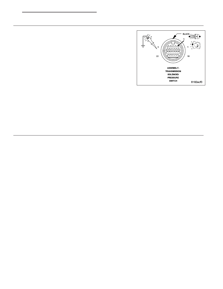
CHECK THE (T20) LINE PRESSURE SOLENOID CONTROL CIRCUIT
Turn the ignition off to the lock position.
Reconnect the TCM C1 harness connector.
Ignition on, engine not running.
With the scan tool actuate the Line Pressure Solenoid.
Using a test light connected to ground, check the (T20) Line Pressure
Solenoid Control circuit in the Transmission Solenoid/Pressure Switch
Assembly harness connector.
NOTE: The test light must illuminate brightly. Compare the bright-
ness to that of a direct connection to the battery.
Does the test light illuminate brightly?
Yes
>> Replace the Line Pressure Solenoid (Valve Body) or the
CVT per the Service Information.
Perform CVT VERIFICATION TEST. (Refer to 21 - TRANSMISSION/TRANSAXLE/AUTOMATIC - CVT -
STANDARD PROCEDURE)
No
>> Using the schematics as a guide, check the Transmission Control Module (TCM) terminals for corrosion,
damage, or terminal push out. Pay particular attention to all power and ground circuits. Check for any
Service Bulletins for possible causes that may apply. If no problems are found, replace the TCM per the
Service Information.
Perform CVT VERIFICATION TEST. (Refer to 21 - TRANSMISSION/TRANSAXLE/AUTOMATIC - CVT -
STANDARD PROCEDURE)
4.
INTERMITTENT WIRING AND CONNECTORS
The conditions necessary to set this DTC are not present at this time.
Using the schematics as a guide, inspect the wiring and connectors specific to this circuit.
Wiggle the wires while checking for shorted and open circuits.
Were there any problems found?
Yes
>> Repair as necessary.
Perform CVT VERIFICATION TEST. (Refer to 21 - TRANSMISSION/TRANSAXLE/AUTOMATIC - CVT -
STANDARD PROCEDURE)
No
>> Test Complete.
PM
AUTOMATIC - CVT-ELECTRICAL DIAGNOSTICS
21 - 219