Dodge Caliber. Manual - part 1164


  Index      Dodge     Dodge Caliber - service repair manual 2007 year


Search            


Content   ..  1162  1163  1164  1165   ..


Dodge Caliber. Manual - part 1164


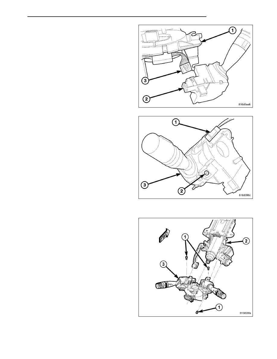
3. Connect the left stalk switch electrical connector.

4. Install the left stalk switch retaining screw.

INSTALLATION

1. Position the SCCM (3) over the steering column

shaft (2).

2. Install the three screws (1).

PM

COLUMN

19 - 43

3. Connect the electrical connectors (2) to the instru-

ment panel harness, ensure wiring is properly
routed. Then check that the connectors, locking
tabs are properly engaged.

4. Install steering column shrouds (Refer to 19 -

STEERING/COLUMN/UPPER SHROUD - INSTAL-
LATION). Be sure all wires are inside of shrouds.

5. Install steering wheel ensuring the flats on hub

align with the clockspring (Refer to 19 - STEER-
ING/COLUMN/STEERING WHEEL - INSTALLA-
TION). Pull the airbag leads through the larger slot.
Ensure leads do not get pinched under the steering
wheel.

NOTE: There is a small wire harness in the steer-
ing wheel and it contains the horn circuits and
speed control circuits.

6. Connect the speed control and horn wire connector

into the clockspring.

7. Pull the grenade pin out of the clockspring.

8. Install the driver airbag, (Refer to 8 - ELECTRICAL/RESTRAINTS/DRIVER AIRBAG - INSTALLATION)

WARNING: Do not connect the battery negative cable (REFER TO 8 - ELECTRICAL/RESTRAINTS - DIAGNO-
SIS AND TESTING - AIRBAG SYSTEM). Personal injury or death may result if the system test is not per-
formed first.

19 - 44

COLUMN

PM

STEERING WHEEL

REMOVAL

WARNING:

Do not place a non-deployed airbag face down on a hard surface, the airbag will propel into the air if
accidentally deployed, and could result in serious or fatal injury.

Disconnect and isolate the battery negative (ground) cable before beginning steering wheel removal or
installation. This will disable the airbag system. Failure to disconnect the battery could result in acciden-
tal airbag deployment and possible personal injury.

Allow the airbag system capacitor to discharge for two minutes before removing the steering wheel or
any airbag system component.

1. Adjust the steering wheel so that the tires are in the STRAIGHT-AHEAD position.

2. Disconnect and isolate the battery negative cable.

3. Remove the driver airbag (3). (Refer to 8 - ELEC-

TRICAL/RESTRAINTS/DRIVER

AIRBAG

-

REMOVAL).

4. Disconnect

the

wiring

connector

(2)

at

the

clockspring.

PM

COLUMN

19 - 45

5. While holding the steering wheel firmly in place,

remove the retaining bolt (2) securing the steering
wheel to the steering column shaft.

CAUTION: When installing a wheel puller on the
steering wheel, be sure the puller jaws are fully
seated around the steering wheel base (1). If the
jaws are not fully seated the jaws may slipped off
the steering wheel when attempting to remove the
steering wheel.
Also, threading the retaining bolt (2) back in the
end of the shaft until approximately 13 mm (0.5
in.) of thread is showing between the wheel and
the head of the bolt allows a safe reaction surface
for the puller to work against.

6. Thread the wheel retaining bolt (2) back into the

end of the shaft until approximately 13 mm (0.5 in.)
of thread is showing between the wheel and the
head of the bolt.

7. Remove the screw for the speed control switch (3)

in order to install the steering wheel puller tool.

8. Install a steering wheel puller on the steering

wheel.

CAUTION: Do not bump or hammer on steering wheel or steering column shaft when removing steering
wheel from steering column.

9. While holding the steering wheel firmly in the STRAIGHT-AHEAD position, remove steering wheel from the steer-

ing column shaft using the puller.

10. Remove the wheel retaining bolt (2) and the steering wheel.

INSTALLATION

1. Confirm that:

a. The front wheels are in the STRAIGHT-AHEAD position.

b. The turn signal stalk is in the neutral position.

CAUTION: Do not install the steering wheel onto the shaft of the steering column by driving it onto the
shaft.

2. Align the steering wheel’s wide mounting spline with the steering column shaft missing spline area and push the

wheel onto the shaft. Make sure the clockspring lines up with the back of the wheel and does not bind.

19 - 46

COLUMN

PM


Content   ..  1162  1163  1164  1165   ..