Dodge Caliber. Manual - part 103


  Index      Dodge     Dodge Caliber - service repair manual 2007 year


Search            


Content   ..  101  102  103  104   ..


Dodge Caliber. Manual - part 103


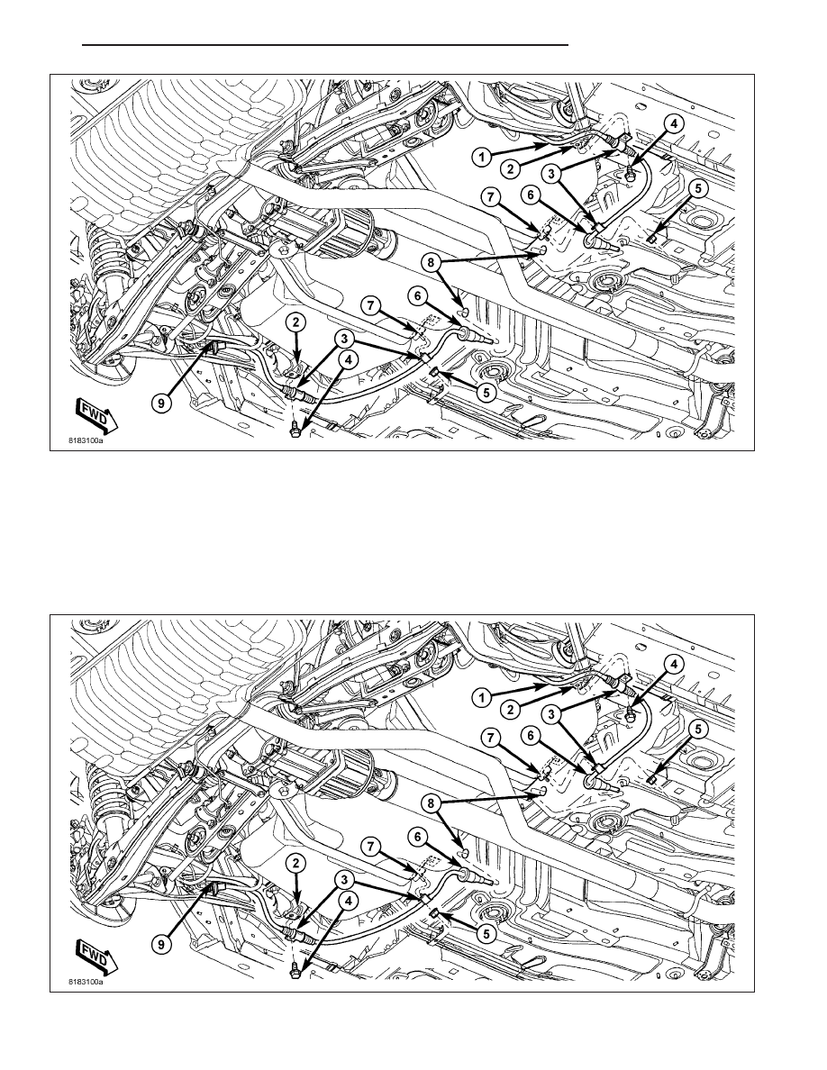
15. Remove the screw (4) securing the cable routing clamp (3) to the body (2).

16. Remove the nut (5) securing the cable routing clamp (3) to the fuel tank strap (7).

17. Remove the parking brake cable (1 - right cable, 9 - left cable) with sealing grommet (6) through the hole (8)

in the floor pan of the vehicle.

INSTALLATION

NOTE: The following procedure applies to either of the two rear parking brake cables.

PM

BRAKES - BASE

5 - 113

1. From underneath, push the parking brake cable through the hole (8) in the floor pan of the vehicle making sure

the cable sealing grommet (6) is installed in the floor pan as far as possible (without going all the way through)
to ensure a good seal.

2. Position the cable routing clamp (3) over the stud on the fuel tank strap (7) and install the nut (5).

3. Position the cable routing clamp (3) and install the screw (4) securing the cable (1 - right cable, 9 - left cable) to

the body (2).

4. Insert the parking brake cable through the hole in

the trailing link and the support plate (3).

5. Install the hair pin (1) securing the parking brake

cable (2) to the brake support plate (3).

6. Install the parking brake shoes (and check adjustment) and components removed to access them. (Refer to 5 -

BRAKES/PARKING BRAKE/SHOES - INSTALLATION)

7. Install tire and wheel assembly (1) (Refer to 22 -

TIRES/WHEELS - INSTALLATION). Install and
tighten wheel mounting nuts (3) to 135 N·m (100 ft.
lbs.).

8. Lower the vehicle.

9. Block the tire and wheel assemblies so the vehicle

does not move with the vehicle parking brake lever
released.

5 - 114

BRAKES - BASE

PM

10. Ensure that the seal grommet on the cable

installed from underneath is fully seated into the
floor pan.

11. Route the parking brake cable under the carpet-

ing, up to the parking brake cable retaining
bracket (4) on the floor pan. Insert the parking
brake cable (3) through the retaining bracket.
Push the cable in until the locking fingers on the
cable retainer lock the cable into place.

CAUTION: A NEW parking brake cable equalizer (2)
must be installed when servicing the parking
brake cables or lever. The equalizer has an inte-
grated bent nail tensioner that needs to be
stretched upon installation placing the correct ten-
sion on the cables.

12. Remove and install a NEW parking brake cable

equalizer (2) on the parking brake lever output
cable.

13. Install the rear parking brake cables (3) into the

equalizer (2) on the parking brake lever output
cable.

14. Ensure that the parking brake cables are correctly

installed on the equalizer and aligned with the
cable track on the parking brake lever.

NOTE: Actuating the parking brake lever to its
fully applied position one time after tightening the
adjustment nut will yield (stretch) the bent nail
portion of the equalizer approximately 1/4 inch.
This process will correctly set the parking brake
cable tension.

15. Adjust parking brake cable tension using the fol-

lowing steps:

a. Place the parking brake lever in the fully

released (down) position.

b. Tighten the adjusting nut (3) on the parking

brake lever output cable until 31 millimeters of
thread is out past the end of the adjustment
nut (1).

c. Actuate the parking brake lever to its fully

applied position one time, then reposition it to
its fully released (down) position.

PM

BRAKES - BASE

5 - 115

16. Raise the vehicle to a point where the rear wheels just clear the floor.

17. Check the rear wheels of the vehicle; they should rotate freely without dragging.

18. Apply the parking brake. Check the rear wheels of the vehicle. They should not rotate.

19. Return the parking brake lever to its fully released (down) position and check the rear wheels. They should

rotate freely without dragging.

20. Apply the parking brake.

21. Lower the vehicle.

22. Install the center console. (Refer to 23 - BODY/

INTERIOR/CENTER

CONSOLE

-

INSTALLA-

TION)

23. Remove the blocks from the tires and wheel

assemblies.

24. Connect the battery negative cable to its post on

the battery.

5 - 116

BRAKES - BASE

PM


Content   ..  101  102  103  104   ..