Dodge Durango (HB). Manual - part 1571


  Index      Dodge     Dodge Durango (HB) - service repair manual 2005 year


Search            


Content   ..  1569  1570  1571  1572   ..


Dodge Durango (HB). Manual - part 1571


1. Recover the refrigerant from the refrigerant system

(Refer to 24 - HEATING & AIR CONDITIONING/
PLUMBING - FRONT - STANDARD PROCEDURE
- REFRIGERANT SYSTEM RECOVERY).

2. Disconnect and isolate the negative battery cable.

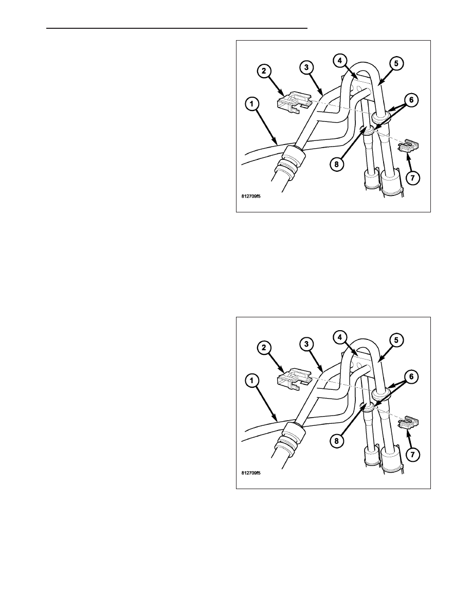
3. Disconnect the A/C suction line (3) from the A/C

compressor and the front A/C expansion valve
(Refer to 24 - HEATING & AIR CONDITIONING/
PLUMBING

-

FRONT/LINE-A/C

SUCTION

-

REMOVAL)

4. Remove the secondary retaining clip (2) from the

refrigerant line coupler (6) on the suction line
extension tube (5)

5. Disconnect the underbody suction line from the

suction line extension tube and remove and discard
the O-ring seal (Refer to 24 - HEATING & AIR
CONDITIONING/PLUMBING

-REAR/COUPLER-

REFRIGERANT LINE - REMOVAL).

6. Install plugs in, or tape over the refrigerant line coupler and the underbody suction line.

7. Remove the A/C suction line from the engine compartment.

INSTALLATION

NOTE: The A/C suction line connects between the A/C evaporator and the A/C compressor. On models
equipped with the rear heating-A/C system, the A/C suction line also includes an extension tube that con-
nects the suction line to the underbody lines.

1. Install the A/C suction line (3) to the A/C compres-

sor and the front A/C expansion valve (Refer to 24
- HEATING & AIR CONDITIONING/PLUMBING -
FRONT/LINE-A/C SUCTION - INSTALLATION).

2. Remove the tape or plugs from the refrigerant line

coupler (6) and the underbody suction line.

3. Lubricate a new rubber O-ring seal with clean

refrigerant oil and install it onto the refrigerant line
coupler. Use only the specified O-ring as it is made
of a special material for the R-134a system. Use
only refrigerant oil of the type recommended for the
A/C compressor in the vehicle.

4. Connect the underbody suction line to the suction

line extension tube (5) (Refer to 24 - HEATING &
AIR CONDITIONING/PLUMBING - REAR/COU-
PLER-REFRIGERANT LINE - INSTALLATION).

5. Install the secondary retaining clip (2) onto the

refrigerant line coupler.

6. Reconnect the negative battery cable.

7. Evacuate the refrigerant system (Refer to 24 - HEATING & AIR CONDITIONING/PLUMBING - FRONT - STAN-

DARD PROCEDURE - REFRIGERANT SYSTEM EVACUATE).

8. Charge the refrigerant system (Refer to 24 - HEATING & AIR CONDITIONING/PLUMBING - FRONT - STAN-

DARD PROCEDURE - REFRIGERANT SYSTEM CHARGE).

HB

PLUMBING - REAR

24 - 477

LINE-UNDERBODY

DESCRIPTION

Models equipped with the rear heating-A/C system use metal lines (1) attached to the vehicle underbody (2) to carry
refrigerant and engine coolant to/and from the rear A/C evaporator and heater core. The underbody A/C lines are
connected to the front suction and liquid lines by spring-lock type couplers and secondary retaining clips (Refer to
24 - HEATING & AIR CONDITIONING/PLUMBING -REAR/COUPLER-REFRIGERANT LINE - DESCRIPTION) and
to the rear HVAC housing (3) by a tapping plate (4) and nut (5). The metal underbody heater lines have rubber hose
ends that are connected to the front heater hoses and the rear HVAC housing by use of spring-clamp type heater
hose clamps. The underbody lines are retained by plastic mounting brackets (6) and screws (7) and can be repaired
(depending on the amount of damage) by using Miller Special Tool Kit 8456-A or equivalent (Refer to 24 - HEATING
& AIR CONDITIONING/PLUMBING - REAR/LINES-UNDERBODY - REMOVAL).

CAUTION: Use only O-ring seals specified for the vehicle. Failure to use the correct O-ring seal will cause
the refrigerant system connections to leak.

The underbody lines can only be removed by lifting the body off of the frame and have no serviceable parts except
for the refrigerant line rubber O-ring seals and the mounting brackets. The O-ring seals used on the refrigerant line
connections are made from a special type of rubber not affected by R-134a refrigerant. The O-ring seals must be
replaced whenever the underbody refrigerant lines are disconnected or removed.

REMOVAL

UNDERBODY LINE REPAIR

WARNING: Refer to the applicable warnings and cautions for this system before performing the following
operation (Refer to 24 - HEATING & AIR CONDITIONING/PLUMBING - FRONT - WARNINGS) and (Refer to 24
- HEATING & AIR CONDITIONING/PLUMBING - FRONT - CAUTIONS). Failure to follow the warnings and cau-
tions could result in possible personal injury or death.

WARNING: This procedure is intended for underbody line repair only. Use of the connector fittings and
Repair Kit 8456-A on any other type of vehicle tubing could cause tube failure resulting in possible personal
injury or death.

24 - 478

PLUMBING - REAR

HB

1. If repairing an underbody refrigerant line, recover

the refrigerant from the refrigerant system (Refer to
24 - HEATING & AIR CONDITIONING/PLUMBING
- FRONT - STANDARD PROCEDURE - REFRIG-
ERANT SYSTEM RECOVERY).

2. If repairing an underbody coolant line, drain the

engine cooling system (Refer to 7 - COOLING -
STANDARD PROCEDURE - COOLING SYSTEM
DRAIN).

3. Disconnect and isolate the negative battery cable.

4. Raise and support the vehicle.

5. Remove the underbody mounting brackets as nec-

essary to gain access to the underbody line(s)
needing repair (Refer to 24 - HEATING & AIR
CONDITIONING/PLUMBING

-

REAR/LINES-UN-

DERBODY - REMOVAL).

6. Mark the cut location(s) on the underbody line(s)

needing repair. Check the Tube Length chart for
the minimum amount of straight tube required (dimension A) for proper connector fitting installation.

7. Using a small pipe cutter or another suitable tool, carefully cut the underbody line(s) needing repair at the loca-

tion(s) previously marked.

TUBE LENGTH

Tube Size

Minimum Tube Length Required

Dimension A Standard Installation

Dimension A Jaw Reversed Installation

3/8 in

28.5 mm (1 1/8 in)

19 - 28.5 mm (3/4 - 1 1/8 in)

1/2 in

28.5 mm (1 1/8 in)

19 - 28.5 mm (3/4 - 1 1/8 in)

5/8 in

31.7 mm (1 1/4 in)

22.2 - 31.7 mm (7/8 - 1 1/4 in)

8. Size a replacement line, same size diameter and

length as the portion of the line(s) removed.

NOTE: A minimum of 28.5 mm (3/4 in) of the line
end must be cleaned in order for the connector fit-
ting to properly seal the repair area.

9. Clean the ends of the line(s) a minimum of 28.5

mm (3/4 in) (dimension A) using the Scoth-Bright
pad provided in special tool Kit 8456-A. Clean the
line end(s) with a rotational motion around the line
to avoid longitudinal scratches in the line.

HB

PLUMBING - REAR

24 - 479

10. Select the proper connector fitting (1) for the size

of the underbody line being repaired. Refer to the
Connector Fitting chart.

11. Apply one drop of Lokprep sealing compound pro-

vided in special tool Kit 8456-A onto each line end
(2).

12. Insert the line ends into the selected connector fit-

ting and rotate the connector fitting a complete
turn to evenly distribute the sealing compound.

CONNECTOR FITTING

Description

Mopar Part Number

3/8 in

5069 002AA

1/2 in

5069 003AA

5/8 in

5069 004AA

13. Select the proper size jaws (1) for the line being

repaired from special tool Kit 8456-A. Refer to the
Jaw Size chart.

14. Assemble the jaws into the tool body (Special Tool

8456-3 in Kit 8456-A) (2).

a. For standard installation, install the jaws with

the rubber gripping pads (3) facing outward.
Refer to Tube Length chart.

b. For reversed installation, remove the rubber

gripping pads and install the jaws with the rub-
ber gripping pad area facing inward. Refer to
Tube Length chart.

JAW SIZE

Description

Miller Part Number

3/8 in

8456-1

1/2 in

8456-4

5/8 in

8456-2

24 - 480

PLUMBING - REAR

HB


Content   ..  1569  1570  1571  1572   ..