Dodge Dakota (R1). Manual - part 780


  Index      Dodge     Dodge Dakota (R1) - service repair manual 2000 year


Search            


Content   ..  778  779  780  781   ..


Dodge Dakota (R1). Manual - part 780


(3) Remove the three screws that secure the stor-

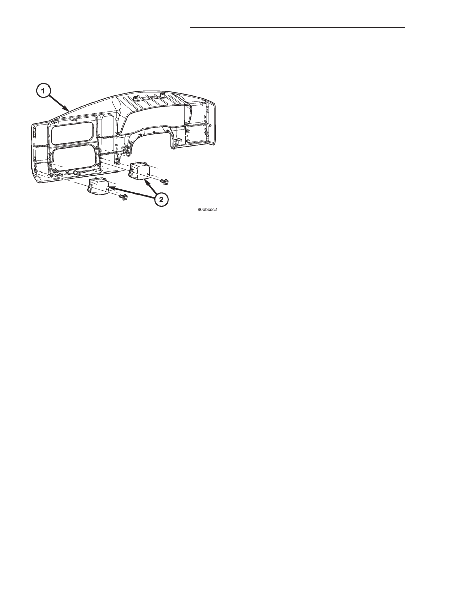
age bin to the back of the cluster bezel (Fig. 22).

(4) Remove the storage bin from the back of the

cluster bezel.

INSTALLATION

A cluster bezel may have one, two, or no storage

bins installed on it, depending upon the vehicle
equipment. A storage bin is used in place of the
optional four-wheel drive transfer case switch and
the optional passenger airbag on/off switch. If the
vehicle is equipped with both of these switches, it
will not have a storage bin installed in the cluster
bezel.

WARNING: ON VEHICLES EQUIPPED WITH AIR-
BAGS, DISABLE THE AIRBAG SYSTEM BEFORE
ATTEMPTING ANY STEERING WHEEL, STEERING
COLUMN, SEAT BELT TENSIONER, OR INSTRU-
MENT PANEL COMPONENT DIAGNOSIS OR SER-
VICE. DISCONNECT AND ISOLATE THE BATTERY
NEGATIVE (GROUND) CABLE, THEN WAIT TWO
MINUTES FOR THE AIRBAG SYSTEM CAPACITOR
TO DISCHARGE BEFORE PERFORMING FURTHER
DIAGNOSIS OR SERVICE. THIS IS THE ONLY SURE
WAY TO DISABLE THE AIRBAG SYSTEM. FAILURE
TO TAKE THE PROPER PRECAUTIONS COULD
RESULT IN ACCIDENTAL AIRBAG DEPLOYMENT
AND POSSIBLE PERSONAL INJURY.

(1) Position the storage bin onto the back of the

cluster bezel (Fig. 22).

(2) Install and tighten the three screws that secure

the storage bin to the back of the cluster bezel.
Tighten the screws to 2 N·m (20 in. lbs.).

(3) Reinstall the cluster bezel onto the instrument

panel. (Refer to 23 - BODY/INSTRUMENT PANEL/
CLUSTER BEZEL - INSTALLATION).

(4) Reconnect the battery negative cable.

TOP COVER

REMOVAL

WARNING: ON VEHICLES EQUIPPED WITH AIR-
BAGS, DISABLE THE AIRBAG SYSTEM BEFORE
ATTEMPTING ANY STEERING WHEEL, STEERING
COLUMN, SEAT BELT TENSIONER, OR INSTRU-
MENT PANEL COMPONENT DIAGNOSIS OR SER-
VICE. DISCONNECT AND ISOLATE THE BATTERY
NEGATIVE (GROUND) CABLE, THEN WAIT TWO
MINUTES FOR THE AIRBAG SYSTEM CAPACITOR
TO DISCHARGE BEFORE PERFORMING FURTHER
DIAGNOSIS OR SERVICE. THIS IS THE ONLY SURE
WAY TO DISABLE THE AIRBAG SYSTEM. FAILURE
TO TAKE THE PROPER PRECAUTIONS COULD
RESULT IN ACCIDENTAL AIRBAG DEPLOYMENT
AND POSSIBLE PERSONAL INJURY.

(1) Disconnect and isolate the battery negative

cable.

(2) Remove the end caps from each end of the

instrument panel. (Refer to 23 - BODY/INSTRU-
MENT PANEL/END CAP - REMOVAL - DRIVER
SIDE) and (Refer to 23 - BODY/INSTRUMENT PAN-
EL/END CAP - REMOVAL - PASSENGER SIDE).

(3) Remove the cluster bezel from the instrument

panel. (Refer to 23 - BODY/INSTRUMENT PANEL/
CLUSTER BEZEL - REMOVAL).

(4) Remove the passenger airbag from the instru-

ment

panel.

(Refer

to

8

-

ELECTRICAL/RE-

STRAINTS/PASSENGER AIRBAG - REMOVAL).

(5) Remove the defroster grille from the instru-

ment panel. (Refer to 23 - BODY/INSTRUMENT
PANEL/DEFROSTER GRILLE - REMOVAL).

(6) Remove the six screws that secure the forward

edge (nearest the windshield) of the top cover to the
instrument panel structural support (Fig. 23).

(7) Remove the screw that secures each outboard

end of the top cover to the instrument panel struc-
tural support beneath the end caps.

(8) Remove the six screws that secure the rear-

ward edge (nearest the passenger compartment) of
the top cover to the instrument panel structural sup-
port.

(9) Remove the top cover from the top of the

instrument panel structural support.

Fig. 22 Storage Bin Remove/Install

1 - CLUSTER BEZEL
2 - STORAGE BIN (2)

23 - 108

INSTRUMENT PANEL SYSTEM

AN

STORAGE BIN (Continued)

INSTALLATION

WARNING: ON VEHICLES EQUIPPED WITH AIR-
BAGS, DISABLE THE AIRBAG SYSTEM BEFORE
ATTEMPTING ANY STEERING WHEEL, STEERING
COLUMN, SEAT BELT TENSIONER, OR INSTRU-
MENT PANEL COMPONENT DIAGNOSIS OR SER-
VICE. DISCONNECT AND ISOLATE THE BATTERY
NEGATIVE (GROUND) CABLE, THEN WAIT TWO
MINUTES FOR THE AIRBAG SYSTEM CAPACITOR
TO DISCHARGE BEFORE PERFORMING FURTHER
DIAGNOSIS OR SERVICE. THIS IS THE ONLY SURE
WAY TO DISABLE THE AIRBAG SYSTEM. FAILURE
TO TAKE THE PROPER PRECAUTIONS COULD
RESULT IN ACCIDENTAL AIRBAG DEPLOYMENT
AND POSSIBLE PERSONAL INJURY.

(1) Position the top cover onto the top of the

instrument panel structural support (Fig. 23).

(2) Install and tighten the six screws that secure

the rearward edge (nearest the passenger compart-
ment) of the top cover to the instrument panel struc-
tural support. Tighten the screws to 2 N·m (20 in.
lbs.).

(3) Install and tighten the screw that secures each

outboard end of the top cover to the instrument panel
structural support beneath the end caps. Tighten the
screws to 2 N·m (20 in. lbs.).

(4) Install and tighten the six screws that secure

the forward edge (nearest the windshield) of the top
cover to the instrument panel structural support.
Tighten the screws to 2 N·m (20 in. lbs.).

(5) Reinstall the defroster grille onto the instru-

ment panel. (Refer to 23 - BODY/INSTRUMENT
PANEL/DEFROSTER GRILLE - INSTALLATION).

(6) Reinstall the passenger airbag into the instru-

ment

panel.

(Refer

to

8

-

ELECTRICAL/RE-

STRAINTS/PASSENGER

AIRBAG

-

INSTALLATION).

(7) Reinstall the cluster bezel onto the instrument

panel. (Refer to 23 - BODY/INSTRUMENT PANEL/
CLUSTER BEZEL - INSTALLATION).

(8) Reinstall the end caps onto each end of the

instrument panel. (Refer to 23 - BODY/INSTRU-
MENT PANEL/END CAP - INSTALLATION).

(9) Reconnect the battery negative cable.

Fig. 23 Top Cover Remove/Install

1 - SCREW (6)
2 - SCREW (2)
3 - TOP COVER
4 - SCREW (6)

AN

INSTRUMENT PANEL SYSTEM

23 - 109

TOP COVER (Continued)

INTERIOR

TABLE OF CONTENTS

page

page

INTERIOR

DESCRIPTION . . . . . . . . . . . . . . . . . . . . . . . . . . 110

FLOOR SHIFT BOOT

REMOVAL . . . . . . . . . . . . . . . . . . . . . . . . . . . . . 110
INSTALLATION . . . . . . . . . . . . . . . . . . . . . . . . . . 111

A-PILLAR TRIM

REMOVAL. . . . . . . . . . . . . . . . . . . . . . . . . . . . . . 111
INSTALLATION . . . . . . . . . . . . . . . . . . . . . . . . . . 111

ASSIST HANDLE

REMOVAL . . . . . . . . . . . . . . . . . . . . . . . . . . . . . 112
INSTALLATION . . . . . . . . . . . . . . . . . . . . . . . . . . 112

B-PILLAR TRIM

REMOVAL . . . . . . . . . . . . . . . . . . . . . . . . . . . . . 112
INSTALLATION . . . . . . . . . . . . . . . . . . . . . . . . . . 113

C-PILLAR TRIM

REMOVAL . . . . . . . . . . . . . . . . . . . . . . . . . . . . . 113
INSTALLATION . . . . . . . . . . . . . . . . . . . . . . . . . . 113

CARPETS AND FLOOR MATS

REMOVAL . . . . . . . . . . . . . . . . . . . . . . . . . . . . . 113
INSTALLATION . . . . . . . . . . . . . . . . . . . . . . . . . . 113

COAT HOOK

REMOVAL . . . . . . . . . . . . . . . . . . . . . . . . . . . . . 114
INSTALLATION . . . . . . . . . . . . . . . . . . . . . . . . . . 114

COWL TRIM COVER

REMOVAL . . . . . . . . . . . . . . . . . . . . . . . . . . . . . 114
INSTALLATION . . . . . . . . . . . . . . . . . . . . . . . . . . 114

DOOR SILL TRIM

REMOVAL . . . . . . . . . . . . . . . . . . . . . . . . . . . . . 114
INSTALLATION . . . . . . . . . . . . . . . . . . . . . . . . . . 114

FLOOR CONSOLE

REMOVAL . . . . . . . . . . . . . . . . . . . . . . . . . . . . . 115
INSTALLATION . . . . . . . . . . . . . . . . . . . . . . . . . . 115

HEADLINER

REMOVAL . . . . . . . . . . . . . . . . . . . . . . . . . . . . . 115
INSTALLATION . . . . . . . . . . . . . . . . . . . . . . . . . . 115

QUARTER TRIM PANEL

REMOVAL . . . . . . . . . . . . . . . . . . . . . . . . . . . . . 116
INSTALLATION . . . . . . . . . . . . . . . . . . . . . . . . . . 116

REAR CAB BACK PANEL TRIM

REMOVAL . . . . . . . . . . . . . . . . . . . . . . . . . . . . . 117
INSTALLATION . . . . . . . . . . . . . . . . . . . . . . . . . . 117

REAR STORAGE BOX

REMOVAL . . . . . . . . . . . . . . . . . . . . . . . . . . . . . 117
INSTALLATION . . . . . . . . . . . . . . . . . . . . . . . . . . 117

REAR VIEW MIRROR

REMOVAL . . . . . . . . . . . . . . . . . . . . . . . . . . . . . 118
INSTALLATION . . . . . . . . . . . . . . . . . . . . . . . . . . 118

SHIFT BEZEL

REMOVAL . . . . . . . . . . . . . . . . . . . . . . . . . . . . . 118
INSTALLATION . . . . . . . . . . . . . . . . . . . . . . . . . . 118

SUN VISORS

REMOVAL . . . . . . . . . . . . . . . . . . . . . . . . . . . . . 119
INSTALLATION . . . . . . . . . . . . . . . . . . . . . . . . . . 119

REAR VIEW MIRROR SUPPORT BRACKET

INSTALLATION . . . . . . . . . . . . . . . . . . . . . . . . . . 119

AIR EXHAUSTER - CAB

REMOVAL . . . . . . . . . . . . . . . . . . . . . . . . . . . . . 120
INSTALLATION . . . . . . . . . . . . . . . . . . . . . . . . . . 120

INTERIOR

DESCRIPTION

CAUTION: Do not attempt to remove interior trim
panels/moldings without first removing the neces-
sary adjacent panels.

To avoid damaging the panels, ensure that all the

screws and clips are removed before attempting to
remove an interior trim panel/molding. Trim panels
are somewhat flexible but can be damaged if
handled improperly.

FLOOR SHIFT BOOT

REMOVAL

(1) Using a small flat blade, pry out insert from

shift knob (Fig. 1).

(2) Remove nut attaching shift knob to gear shift.
(3) Pull knob off gear shift.
(4) Using a small flat bladed screwdriver pry up

one corner of the bezel/boot assembly. Do not sepa-
rate the boot from the bezel.

23 - 110

INTERIOR

AN

(5) Lift the boot/bezel assembly off of the floor

panel and over the gear shift (Fig. 2) and (Fig. 3).

INSTALLATION - FLOOR SHIFT BOOT

(1) Position shift boot/bezel assembly on gear shift.
(2) Press shift boot/bezel onto the floor panel.
(3) Push knob onto gear shift.
(4) Install nut attaching shift knob to gear shift.
(5) Press insert into shift knob.

A-PILLAR TRIM

REMOVAL

(1) Remove A-pillar grab handle, if equipped.
(2) Remove screws from cowl trim cover.
(3) Remove cowl trim cover.
(4) Grasp A-pillar trim and pull outward to disen-

gage clips attaching A-pillar trim to A-pillar (Fig. 4).

(5) Separate A-pillar trim from vehicle.

INSTALLATION

(1) Position A-pillar trim at A-pillar, align clips

and press into place.

(2) Install cowl trim cover.
(3) Install A-pillar grab handle, if equipped.

Fig. 1 Shift Knob Insert

1 - KNOB
2 - KNOB INSERT
3 - SHIFT BOOT
4 - FLOOR PAN
5 - TRANSFER CASE LEVER
6 - CARPET
7 - PLATE
8 - GEAR SHIFT

Fig. 2 Shift Boot—Manual Transmission

1 - KNOB
2 - KNOB INSERT
3 - SHIFT BOOT
4 - FLOOR PAN
5 - CARPET
6 - PLATE
7 - GEAR SHIFT

Fig. 3 Shift Boot—Transfer Case

1 - KNOB INSERT
2 - KNOB
3 - TRANSFER CASE SHIFT LEVER
4 - FLOOR PAN
5 - PLATE
6 - BEZEL
7 - TRANSFER CASE SHIFT BOOT

AN

INTERIOR

23 - 111

FLOOR SHIFT BOOT (Continued)


Content   ..  778  779  780  781   ..