Dodge Dakota (R1). Manual - part 601


  Index      Dodge     Dodge Dakota (R1) - service repair manual 2000 year


Search            


Content   ..  599  600  601  602   ..


Dodge Dakota (R1). Manual - part 601


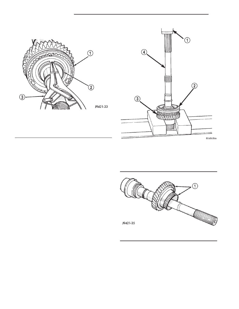
(16) Remove fifth-reverse synchro hub snap ring

(Fig. 46).

(17) Remove fifth-reverse synchro hub and sleeve

with a press (Fig. 47).

(18) Remove reverse gear and needle bearing (Fig.

48).

REVERSE IDLER

(1) Remove idler gear snap rings (Fig. 49).
(2) Remove thrust washer, wave washer, thrust

plate and idler gear from shaft.

(3) Remove idler gear needle bearing from shaft.

CLEANING

Clean the gears, shafts, shift components and

transmission housings with a standard parts clean-
ing solvent. Do not use acid or corrosive base sol-
vents. Dry all parts except bearings with compressed
air.

Clean the shaft bearings with a mild solvent such

as Mopar® degreasing solvent, Gunk, or similar sol-
vents. Do not dry the bearings with compressed air.
Allow the bearings to either air dry, or wipe them dry
with clean shop towels.

Fig. 46 FIFTH-REVERSE SYNCHRO HUB SNAP

RING

1 - FIFTH-REVERSE SYNCHRO HUB AND SLEEVE
2 - SYNCHRO HUB SNAP RING
3 - SNAP RING PLIERS

Fig. 47 FIFTH-REVERSE SYNCHRO HUB AND

SLEEVE

1 - PRESS
2 - FIFTH-REVERSE SYNCHRO HUB AND SLEEVE
3 - REVERSE GEAR
4 - OUTPUT SHAFT

Fig. 48 REVERSE GEAR AND NEEDLE BEARING

1 - REVERSE GEAR AND NEEDLE BEARING

21 - 48

MANUAL - NV3500

AN

MANUAL - NV3500 (Continued)

INSPECTION

SHIFT LEVER ASSEMBLY

The shift lever assembly is not serviceable. Replace

the lever and shift tower as an assembly if the tower,
lever, lever ball, or internal components are worn, or
damaged.

SHIFT SHAFT AND FORKS

Inspect the shift fork interlock arms and synchro

sleeve contact surfaces (Fig. 50). Replace any fork
exhibiting wear or damage in these areas. Do not
attempt to salvage shift forks.

Check condition of the shift shaft detent plunger

and spring. The plunger should be smooth and free of
nicks, or scores. The plunger spring should be
straight and not collapsed, or distorted. Minor
scratches, or nicks on the plunger can be smoothed
with 320/400 grit emery soaked in oil. Replace the
plunger and spring if in doubt about condition. Check
condition of detent plunger bushings. Replace if dam-
aged.

Inspect the shift shaft, shift shaft bushing and

bearing, the shaft lever, and the lever bushing that
fits over the lever. Replace the shaft if bent, cracked,
or severely scored. Minor burrs, nicks, or scratches
can be smoothed off with 320/400 grit emery cloth
followed by polishing with crocus cloth. Replace the
shift shaft bushing or bearing if damaged.

Replace the shaft lever and bushing if either part

is deformed, or worn. Do not attempt to salvage these
parts as shift fork binding will occur. Replace the roll
pin that secures the lever to the shaft.

FRONT/REAR HOUSINGS AND BEARING
RETAINERS

Inspect the housings carefully. Look for cracks,

stripped threads, scored mating surfaces, damaged
bearing bores, or worn dowel pin holes. Minor nicks
on mating surfaces can be dressed off with a fine file,
or emery cloth. Damaged threads can be renewed by
either re-tapping or installing Helicoil inserts.

NOTE: The front housing contains the countershaft
front bearing race. The rear housing contains the
countershaft rear bearing race. Be advised that
these components are NOT serviceable items. The
front housing will have to be replaced if the coun-
tershaft bearing race is loose, worn, or damaged.
The rear housing will have to be replaced if the
countershaft rear bearing race is loose, worn, or
damaged.

Inspect the input shaft bearing retainer. Be sure

the release bearing slide surface of the retainer is in
good condition. Minor nicks on the surface can be
smoothed off with 320/420 grit emery cloth and final
polished with oil coated crocus cloth. Replace the
retainer seal if necessary.

Inspect the output shaft bearing retainer. Be sure

the U-shaped retainer is flat and free of distortion.
Replace the retainer if the threads are damaged, or if
the retainer is bent, or cracked.

COUNTERSHAFT BEARINGS AND RACES

The countershaft bearings and races are machine

lapped during manufacture to form matched sets.
The bearings and races should not be interchanged.

Fig. 49 REVERSE IDLER COMPONENTS

1 - SNAP RING
2 - FLAT WASHER
3 - WAVE WASHER
4 - THRUST WASHER
5 - REVERSE IDLER GEAR

6 - IDLER GEAR BEARING
7 - IDLER SHAFT
8 - THRUST WASHER
9 - SNAP RING
10 - THRUST WASHER LOCKBALLS

AN

MANUAL - NV3500

21 - 49

MANUAL - NV3500 (Continued)

NOTE: The bearing races are a permanent press fit
in the housings and are NOT serviceable. If a bear-
ing race becomes damaged, it will be necessary to
replace the front or rear housing as necessary. A
new countershaft bearing will be supplied with each
new housing for service use.

The countershaft bearings can be installed back-

wards if care is not exercised. The bearing roller cage
is a different diameter on each side. Be sure the
bearing is installed so the large diameter side of the
cage is facing the countershaft gear (Fig. 51). The
small diameter side goes in the bearing race.

REVERSE IDLER COMPONENTS

Inspect the idler gear, bearing, shaft, thrust

washer, wave washer and thrust plate. Replace the
bearing if any of the needle bearing rollers are worn,
chipped, cracked, flat-spotted, or brinnelled. Also
replace the bearing if the plastic bearing cage is
damaged or distorted.

Replace the thrust washer, wave washer, or thrust

plate if cracked, chipped, or worn. Replace the idler
gear if the teeth are chipped, cracked or worn thin.
Replace the shaft if worn, scored, or the bolt threads
are damaged beyond repair. Replace the support seg-
ment if cracked, or chipped and replace the idler
attaching bolts if the threads are damaged.

Fig. 50 Shift Forks And Shaft

1 - SHIFT SHAFT
2 - SHAFT LEVER
3 - SHAFT LEVER BUSHING

4 - 3-4 SHIFT FORK
5 - 1-2 SHIFT FORK
6 - FIFTH-REVERSE SHIFT FORK

Fig. 51 Countershaft Bearings

1 - COUNTERSHAFT
2 - BEARING CAGE

21 - 50

MANUAL - NV3500

AN

MANUAL - NV3500 (Continued)

Shift Socket

Inspect the shift socket for wear or damage.

replace the socket if the roll pin, or shift shaft bores
are damaged. Minor nicks in the shift lever ball seat
in the socket can be smoothed down with 400 grit
emery or wet/dry paper. Replace the socket if the ball
seat is worn, or cracked. Do not reuse the original
shift socket roll pin. Install a new pin during reas-
sembly. The socket roll pin is approximately is
approximately 33 mm (1-1/4 in.) long.

Output Shaft And Geartrain

Inspect all of the gears for worn, cracked, chipped,

or broken teeth. Also check condition of the bearing
bore in each gear. The bores should be smooth and
free of surface damage. Discoloration of the gear
bores is a normal occurrence and is not a reason for
replacement. Replace gears only when tooth damage
has occurred, or if the bores are brinnelled or
severely scored.

Inspect the shaft splines and bearings surfaces.

Minor nicks on the bearing surfaces can be smoothed
with 320/420 grit emery and final polished with cro-
cus cloth. Replace the shaft if the splines are dam-
aged or bearing surfaces are deeply scored, worn, or
brinnelled.

ASSEMBLY

Sealers are used at all case joints. Usa Mopar Gas-

ket Maker for all case joints and Mopar silicone
sealer or equivalent, for the input shaft bearing
retainer. Apply these products as indicated in the
assembly procedures.

CAUTION: The transmission shift components must
be in the Neutral position during assembly. This
prevents damage to the synchro and shift compo-
nents when the housings are installed.

SYNCHRONIZER

To assemble each synchro install the springs,

struts and detent balls one at a time as follows:

(1) Slide the sleeve part way onto the hub. Leave

enough room to install the spring in the hub and the
strut in the hub groove.

(2) Install the first spring in the hub. Then install

a strut over the spring. Be sure the spring is seated
in the spring bore in the strut.

(3) Slide the sleeve onto the hub just far enough to

hold the first strut and spring in place.

(4) Place the detent ball in the top of the strut.

Then carefully work the sleeve over the ball to hold
it in place. Use a small flat blade screwdriver to
press the ball into place while moving the sleeve over
it.

(5) Repeat

the

procedure

for

the

remaining

springs, struts and balls. Tape or rubber band each
strut and ball to temporarily secure as they are
installed.

(6) Verify synchro springs, struts and detent balls

are all in place (Fig. 52).

OUTPUT SHAFT

Lubricate shaft, gears and bearings with recom-

mended lubricant during assembly. Petroleum jelly
can be used to hold parts in place. Check bearing
surfaces of output shaft for nicks or scratches.
Smooth surfaces with 320/400 grit emery cloth if nec-
essary. Apply oil to emery cloth and shaft surface
before polishing.

Inspect and replace any synchro ring if worn or

damage. Immerse each synchro ring in lubricant
before installation.

(1) Lubricate and install reverse gear needle bear-

ing on shaft (Fig. 53). Slide bearing up against shoul-
der on output shaft.

(2) Install reverse gear over needle bearing (Fig.

54).

(3) Install brass synchro ring on reverse gear (Fig.

55).

(4) Assemble fifth-reverse synchro hub, sleeve,

struts, springs and detent balls, if not previously
done.

Fig. 52 SYNCHRONIZER COMPONENTS

1 - SLEEVE
2 - HUB SHOULDER
3 - SPRING (3)
4 - STRUT (3)
5 - DETENT BALL (3)
6 - HUB

AN

MANUAL - NV3500

21 - 51

MANUAL - NV3500 (Continued)


Content   ..  599  600  601  602   ..