Dodge Dakota (R1). Manual - part 475


  Index      Dodge     Dodge Dakota (R1) - service repair manual 2000 year


Search            


Content   ..  473  474  475  476   ..


Dodge Dakota (R1). Manual - part 475


INSPECTION

Measure valve stems for wear. If wear exceeds

0.051 mm (0.002 in.), replace the valve.

Measure valve stem guide clearance as follows:
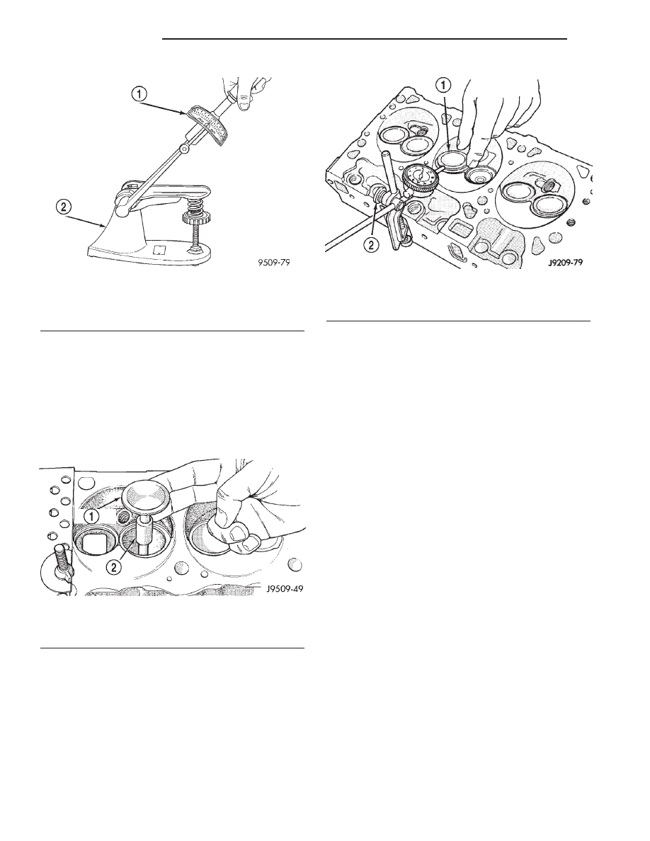
(1) Install Valve Guide Sleeve Tool C-3973 over

valve stem and install valve (Fig. 17). The special
sleeve places the valve at the correct height for
checking with a dial indicator.

(2) Attach dial indicator Tool C-3339 to cylinder

head and set it at right angles to valve stem being
measured (Fig. 18).

(3) Move valve to and from the indicator. The total

dial indicator reading should not exceed 0.432 mm
(0.017 in.). Ream the guides for valves with oversize
stems if dial indicator reading is excessive or if the
stems are scuffed or scored.

INSTALLATION

(1) Clean

valves

thoroughly.

Discard

burned,

warped and cracked valves.

(2) Remove carbon and varnish deposits from

inside of valve guides with a reliable guide cleaner.

(3) Measure valve stems for wear. If wear exceeds

0.051 mm (0.002 inch), replace the valve.

(4) Coat valve stems with lubrication oil and insert

them in cylinder head.

(5) If valves or seats are reground, check valve

stem height. If valve is too long, replace cylinder
head.

(6) Install new seals on all valve guides. Install

valve springs and valve retainers.

(7) Compress valve springs with Valve Spring

Compressor Tool MD-998772A and adapter 6716A,
install locks and release tool. If valves and/or seats
are ground, measure the installed height of springs.
Make sure the measurement is taken from bottom of
spring seat in cylinder head to the bottom surface of
spring retainer. If spacers are installed, measure
from the top of spacer. If height is greater than 42.86
mm (1-11/16 inches), install a 1.587 mm (1/16 inch)
spacer in head counterbore. This should bring spring
height back to normal 41.27 to 42.86 mm (1-5/8 to
1-11/16 inch).

(8) Install cylinder head (Refer to 9 - ENGINE/

CYLINDER HEAD - INSTALLATION).

Fig. 16 Testing Valve Spring for Compressed

Length

1 - TORQUE WRENCH
2 - VALVE SPRING TESTER

Fig. 17 Positioning Valve with Tool C-3973

1 - VALVE
2 - SPACER TOOL

Fig. 18 Measuring Valve Guide Wear

1 - VALVE
2 - SPECIAL TOOL C-3339

9 - 88

ENGINE 3.9L

AN

INTAKE/EXHAUST VALVES & SEATS (Continued)

ENGINE BLOCK

CLEANING

Clean cylinder block thoroughly and check all core

hole plugs for evidence of leakage.

INSPECTION

Examine block for cracks or fractures.
The cylinder walls should be checked for out-of-

round and taper. Refer to Honing Cylinder Bores in
the Service Procedures portion of this Section.

Inspect the oil line plug, the oil line plug is located

in the vertical passage at the rear of the block
between the oil-to-filter and oil-from-filter passages
(Fig. 19) . Improper installation or missing plug could
cause erratic, low, or no oil pressure.

The oil plug must come out the bottom. Use flat

dowel, down the oil pressure sending unit hole from
the top, to remove oil plug.

(1) Remove oil pressure sending unit from back of

block.

(2) Insert a 3.175 mm (1/8 in.) finish wire, or

equivalent, into passage.

(3) Plug should be 190.0 to 195.2 mm (7-1/2 to

7-11/16 in.) from machined surface of block (Fig. 19) .
If plug is too high, use a suitable flat dowel to posi-
tion properly.

(4) If plug is too low, remove oil pan and No. 4

main bearing cap. Use suitable flat dowel to position
properly . Coat outside diameter of plug with Mopar

t

Stud and Bearing Mount Adhesive. Plug should be
54.0 to 57.7 mm (2-1/8 to 2-5/16 in.) from bottom of
the block.

CAMSHAFT & BEARINGS (IN
BLOCK)

REMOVAL—CAMSHAFT BEARINGS

(1) With engine completely disassembled, drive out

rear cam bearing core hole plug.

(2) Install proper size adapters and horseshoe

washers (part of Camshaft Bearing Remover/Installer
Tool C-3132-A) at back of each bearing shell. Drive
out bearing shells (Fig. 20).

REMOVAL—CAMSHAFT

(1) Disconnect battery negative cable.
(2) Remove radiator. (Refer to 7 - COOLING/EN-

GINE/RADIATOR - REMOVAL).

(3) Remove

intake

manifold.

(Refer

to

9

-

ENGINE/MANIFOLDS/INTAKE

MANIFOLD

-

REMOVAL).

(4) Remove distributor assembly (Refer to 8 -

ELECTRICAL/IGNITION CONTROL/DISTRIBUTOR
- REMOVAL).

(5) Remove cylinder head covers (Refer to 9 -

ENGINE/CYLINDER

HEAD/CYLINDER

HEAD

COVER(S) - REMOVAL).

Fig. 19 Oil Line Plug

1 - RIGHT OIL GALLERY
2 - CYLINDER BLOCK
3 - OIL FROM FILTER TO SYSTEM
4 - OIL TO FILTER
5 - FROM OIL PUMP
6 - CRANKSHAFT
7 - PLUG

Fig. 20 Camshaft Bearings Removal and Installation

with Tool C-3132-A

1 - SPECIAL TOOL C-3132A

AN

ENGINE 3.9L

9 - 89

(6) Remove rocker arms (Refer to 9 - ENGINE/

CYLINDER HEAD/ROCKER ARM / ADJUSTER
ASSY - REMOVAL).

(7) Remove push rods and tappets (Refer to 9 -

ENGINE/ENGINE BLOCK/HYDRAULIC LIFTERS
(CAM IN BLOCK) - REMOVAL). Identify each part
so it can be installed in the original locations.

(8) Remove timing chain cover. (Refer to 9 -

ENGINE/VALVE TIMING/TIMING BELT / CHAIN
COVER(S) - REMOVAL).

(9) Align timing marks (Fig. 21) and remove tim-

ing chain and sprockets.

(10) Remove the three tensioner to block mounting

bolts and remove tensioner.

(11) Install a long bolt into front of camshaft to aid

in removal of the camshaft. Remove camshaft, being
careful not to damage cam bearings with the cam
lobes.

INSTALLATION—CAMSHAFT BEARINGS

(1) Install new camshaft bearings with Camshaft

Bearing Remover/Installer Tool C-3132-A by sliding
the new camshaft bearing shell over proper adapter.

(2) Position rear bearing in the tool. Install horse-

shoe lock and, by reversing removal procedure, care-
fully drive bearing shell into place.

(3) Install remaining bearings in the same man-

ner. Bearings must be carefully aligned to bring oil
holes into full register with oil passages from the
main bearing. If the camshaft bearing shell oil holes
are not in exact alignment, remove and install them

correctly. Install a new core hole plug at the rear of
camshaft. Be sure this plug does not leak.

INSTALLATION—CAMSHAFT

(1) Lubricate camshaft lobes and camshaft bearing

journals and insert the camshaft to within 51 mm (2
inches) of its final position in cylinder block.

(2) Install Camshaft Holding Tool C-3509 with

tongue back of distributor drive gear (Fig. 22) .

Fig. 21 Alignment of Timing Marks

1 - TIMING MARKS

Fig. 22 Camshaft Holding Tool C-3509 (Installed

Position)

1 - SPECIAL TOOL C-3509
2 - DRIVE GEAR
3 - DISTRIBUTOR LOCK BOLT

Fig. 23 Compressing Tensioner Shoe For Timing

Chain Installation

1 - SCREWDRIVER
2 - INSERT PIN HERE

9 - 90

ENGINE 3.9L

AN

CAMSHAFT & BEARINGS (IN BLOCK) (Continued)

(3) Hold tool in position with a distributor lock-

plate bolt. This tool will restrict camshaft from being
pushed in too far and prevent knocking out the welch

plug in rear of cylinder block. Tool should remain
installed until the camshaft and crankshaft
sprockets and timing chain have been installed.

(4) Install timing chain tensioner. Torque bolts to

24 N·m (210 in. lbs.) torque.

(5) Compress tensioner shoe (Fig. 23) and install a

suitable sized pin to retain shoe for chain installa-
tion.

(6) Place both camshaft sprocket and crankshaft

sprocket on the bench with timing marks on an exact
imaginary center line through both camshaft and
crankshaft bores.

(7) Place timing chain around both sprockets.
(8) Turn crankshaft and camshaft to line up with

keyway location in crankshaft sprocket and in cam-
shaft sprocket.

(9) Lift sprockets and chain (keep sprockets tight

against the chain in position as described).

(10) Slide both sprockets evenly over their respec-

tive shafts and use a straightedge to check alignment
of timing marks (Fig. 24) .

(11) Install the camshaft bolt/cup washer. Tighten

bolt to 68 N·m (50 ft. lbs.) torque.

(12) Measure camshaft end play (Fig. 25). (Refer to

9 - ENGINE - SPECIFICATIONS) for proper clear-
ance. If not within limits, install a new timing chain
tensioner.

(13) Each tappet reused must be installed in the

same position at which it was removed. When cam-
shaft is replaced, all of the tappets must be
replaced.
Install hydraulic tappets (Refer to 9 -
ENGINE/ENGINE BLOCK/HYDRAULIC LIFTERS
(CAM IN BLOCK) - INSTALLATION).

(14) Install timing chain cover (Refer to 9 -

ENGINE/VALVE TIMING/TIMING BELT / CHAIN
COVER(S) - INSTALLATION).

(15) Install intake manifold (Refer to 9 - ENGINE/

MANIFOLDS/INTAKE MANIFOLD - INSTALLA-
TION).

(16) Install distributor (Refer to 8 - ELECTRICAL/

IGNITION CONTROL/DISTRIBUTOR - INSTALLA-
TION).

(17) Install cylinder head covers (Refer to 9 -

ENGINE/CYLINDER

HEAD/CYLINDER

HEAD

COVER(S) - INSTALLATION).

(18) Install radiator (Refer to 7 - COOLING/EN-

GINE/RADIATOR - INSTALLATION).

(19) Fill cooling system (Refer to 7 - COOLING -

STANDARD PROCEDURE).

(20) Connect battery negative cable.
(21) Start engine and check for leaks.

Fig. 24 Alignment of Timing Marks

1 - TIMING MARKS

Fig. 25 Checking Camshaft End Play

1 - SCREWDRIVER
2 - DIAL INDICATOR
3 - CAM SPROCKET

AN

ENGINE 3.9L

9 - 91

CAMSHAFT & BEARINGS (IN BLOCK) (Continued)


Content   ..  473  474  475  476   ..