Dodge Dakota (R1). Manual - part 362


  Index      Dodge     Dodge Dakota (R1) - service repair manual 2000 year


Search            


Content   ..  360  361  362  363   ..


Dodge Dakota (R1). Manual - part 362


be properly installed. Position the wiper arm pivot
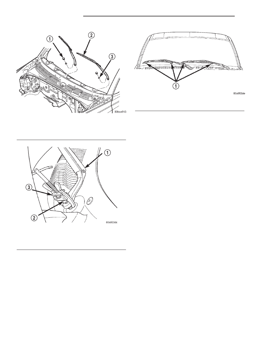
ends onto the wiper pivots so that the lower edge of
the blade is aligned with the wiper alignment lines
concealed in the upper margin of the lower wind-
shield blackout area, ± 15 mm (± 0.59 in.) (Fig. 9).

(2) Once the wiper blade is aligned, lift the wiper

arm away from the windshield slightly to relieve the
spring tension on the pivot end and push the pivot
hole on the end of the wiper arm down over the
wiper pivot shaft.

(3) Install and tighten the nut that secures the

wiper arm to the wiper pivot shaft. Tighten the nut
to 23.7 N·m (210 in. lbs.).

(4) Wet the windshield glass, then operate the wip-

ers. Turn the wiper switch to the Off position, then
check for the correct wiper arm position and readjust
as required.

(5) Reinstall the plastic nut cap onto the wiper

arm pivot nut.

WIPER BLADE

DESCRIPTION

Each wiper blade is secured by an integral latching

pivot block to the hook formation on the tip of the
wiper arms, and rests on the glass near the base of
the windshield when the wipers are not in operation.
The wiper blade consists of the following components:

• Superstructure - The superstructure includes

several stamped steel bridges and links with claw
formations that grip the wiper blade element. The
driver side and passenger side wiper blades are not
interchangeable. The superstructure of the driver
side blade features an additional bridge, which pro-
vides an additional set of claws to retain the wiper
squeegees. Their are eight sets of claws on the driver
side, and six sets of claws used on the passenger
side. Also included in this unit is the latching,
molded plastic pivot block that secures the super-
structure to the wiper arm. All of the metal compo-
nents of the wiper blade have a satin black finish
applied.

• Element - The wiper element or squeegee is the

resilient rubber member of the wiper blade that con-
tacts the glass.

• Flexor - The flexor is a rigid metal component

running along the length of each side of the wiper
element where it is gripped by the claws of the
superstructure.

All Dakota truck models have two 50 centimeter

(19.69 inch) wiper blades with non-replaceable rub-
ber elements (squeegees). These wiper blades also

Fig. 7 Wiper Arm Remove/Install

1 - NUT CAP
2 - WIPER ARM AND BLADE
3 - NUT

Fig. 8 Wiper Arm Puller - Typical

1 - WIPER ARM
2 - WIPER PIVOT
3 - BATTERY TERMINAL PULLER

Fig. 9 Wiper Arm Installation

1 - WIPER ALIGNMENT LINES ± 15 mm (± 0.59 in.)

8R - 14

WIPERS/WASHERS

AN

WIPER ARM (Continued)

include an anti-lift feature. The wiper blades cannot
be adjusted or repaired. If faulty, worn, or damaged
the entire wiper blade unit must be replaced.

OPERATION

The wiper blade is moved back and forth across the

glass by the wiper arms when the wipers are being
operated. The wiper blade superstructure is the flex-
ible frame that grips the wiper blade element and
evenly distributes the force of the spring-loaded
wiper arm along the length of the element. The com-
bination of the wiper arm force and the flexibility of
the superstructure makes the element conform to
and maintain proper contact with the glass, even as
the blade is moved over the varied curvature found
across the glass surface. The wiper element flexor
provides the claws of the blade superstructure with a
rigid, yet flexible component on the element which
can be gripped. The rubber element is designed to be
stiff enough to maintain an even cleaning edge as it
is drawn across the glass, but resilient enough to
conform to the glass surface and flip from one clean-
ing edge to the other each time the wiper blade
changes directions.

REMOVAL

NOTE: The driver side and passenger side wiper
blades are not interchangeable. The driver side
wiper blade has an extra bridge and eight pairs of
claws securing the wiper element. The passenger
side wiper blade has six pairs of claws securing the
wiper element. The notched retainer end of both
wiper elements should always be oriented towards
the end of the wiper blade that is nearest to the
wiper pivot.

(1) Turn the wiper control knob on the end of the

multi-function switch control stalk to the On posi-
tion. Cycle the wiper blades to a convenient working
location on the windshield by turning the ignition
switch to the On and Off positions.

(2) Lift the wiper arm to raise the wiper blade and

element off of the glass.

(3) To remove the wiper blade from the wiper arm,

push the pivot block latch release tab under the tip
of the arm and slide the blade away from the tip
towards the pivot end of the arm far enough to dis-
engage the pivot block from the hook (Fig. 10).

(4) Extract the hook formation on the tip of the

wiper arm from the opening in the wiper blade
superstructure ahead of the wiper blade pivot block/
latch unit.

CAUTION: Do not allow the wiper arm to spring
back against the glass without the wiper blade in
place or the glass may be damaged.

(5) Gently lower the wiper arm tip onto the glass.

INSTALLATION

NOTE: The driver side and passenger side wiper
blades are not interchangeable. The driver side
wiper blade has an extra bridge and eight pairs of
claws securing the wiper element. The passenger
side wiper blade has six pairs of claws securing the
wiper element. The notched retainer end of both
wiper elements should always be oriented towards
the end of the wiper blade that is nearest to the
wiper pivot.

(1) Lift the wiper arm off of the windshield glass.
(2) Position the wiper blade near the hook forma-

tion on the tip of the arm with the notched retainer
for the wiper element oriented towards the end of the
wiper arm that is nearest to the wiper pivot.

(3) Insert the hook formation on the tip of the

wiper arm through the opening in the wiper blade
superstructure ahead of the wiper blade pivot block/
latch unit far enough to engage the pivot block with
the hook (Fig. 10).

(4) Slide the wiper blade pivot block/latch up into

the hook formation on the tip of the wiper arm until
the latch release tab snaps into its locked position.

(5) Gently lower the wiper blade onto the glass.

WIPER MODULE

DESCRIPTION

The wiper module is secured with screws through

four rubber grommet-type insulators to the cowl ple-
num panel and concealed within the cowl plenum
area beneath the cowl plenum cover/grille panel. The
ends of the wiper pivot shafts that protrude through
dedicated openings in the cowl plenum cover/grille
panel to drive the wiper arms and blades are the
only visible components of the wiper module. The

Fig. 10 Wiper Blade Remove/Install - Typical

1 - RELEASE TAB

AN

WIPERS/WASHERS

8R - 15

WIPER BLADE (Continued)

wiper module consists of the following major compo-
nents:

• Bracket - The wiper module bracket consists of

a long tubular steel main member that has a
stamped pivot bracket formation near each end
where the two wiper pivots are secured. A stamped
steel mounting plate for the wiper motor is secured
with welds near the center of the main member.

• Crank Arm - The wiper motor crank arm is a

stamped steel unit that has a slotted hole on the
driven end that is secured to the wiper motor output
shaft with a nut, and has a ball stud secured to the
drive end.

• Linkage - The two wiper linkage members are

each constructed of stamped steel. A driver side drive
link with a plastic socket-type bushing in the left
end, and a plastic sleeve-type bushing in the right
end. Socket bushing is snap-fit over the pivot ball
stud on the left pivot, while the sleeve bushing is fit
over the longer wiper motor crank arm pivot stud.
The passenger side drive link has a plastic socket-
type bushing on each end. One end of this drive link
is snap-fit over the pivot ball stud on the right pivot,
while the other end is snap-fit over the exposed end
of the longer ball stud on the wiper motor crank arm.

• Motor - The wiper motor is secured with three

screws to the motor mounting plate near the center
of the wiper module bracket. The wiper motor output
shaft passes through a hole in the module bracket,
where a nut secures the wiper motor crank arm to
the motor output shaft. The two-speed permanent
magnet wiper motor features an integral transmis-
sion, an internal park switch, and an internal Posi-
tive Temperature Coefficient (PTC) circuit breaker.

• Pivots - The two wiper pivots are secured to the

ends of the wiper module bracket. The crank arms
that extend from the bottom of the pivot shafts each
have a ball stud on their end. The upper end of each
pivot shaft where the wiper arms will be fastened
each has an externally serrated drum secured to it.

The wiper module cannot be adjusted or repaired.

If any component of the module is faulty or damaged,
the entire wiper module unit must be replaced.

OPERATION

The wiper module operation is controlled by the

vehicle operator through battery current inputs
received by the wiper motor from the multi-function
switch on the steering column. The wiper motor
speed is controlled by current flow to either the low
speed or the high speed set of brushes. The park
switch is a single pole, single throw, momentary
switch within the wiper motor that is mechanically
actuated by the wiper motor transmission compo-
nents. The park switch alternately closes the wiper
park switch sense circuit to ground or to battery cur-

rent, depending upon the position of the wipers on
the glass. This feature allows the motor to complete
its current wipe cycle after the wiper system has
been turned Off, and to park the wiper blades in the
lowest portion of the wipe pattern. The automatic
resetting circuit breaker protects the motor from
overloads. The wiper motor crank arm, the two wiper
linkage members, and the two wiper pivots mechan-
ically convert the rotary output of the wiper motor to
the back and forth wiping motion of the wiper arms
and blades on the glass.

REMOVAL

(1) Disconnect and isolate the battery negative

cable.

(2) Remove the wiper arms from the wiper pivots.

(Refer to 8 - ELECTRICAL/WIPERS/WASHERS/
WIPER ARMS - REMOVAL).

(3) Remove the cowl plenum cover/grille panel

from the cowl plenum. (Refer to 23 - BODY/EXTERI-
OR/COWL GRILLE - REMOVAL).

(4) Remove the four screws that secure the wiper

module bracket to the cowl plenum panel and the
dash panel (Fig. 11).

(5) Reach into the cowl plenum to move the wiper

module far enough to access the wiper module elec-
trical connections.

Fig. 11 Wiper Module Remove/Install

1 - WIPER MODULE
2 - SCREW (4)
3 - WIRE HARNESS CONNECTOR

8R - 16

WIPERS/WASHERS

AN

WIPER MODULE (Continued)

(6) Disconnect the headlamp and dash wire har-

ness connector for the wiper motor from the wiper
motor pigtail wire connector.

(7) Disconnect the headlamp and dash wire har-

ness ground connector from the wiper motor ground
terminal.

(8) Remove the wiper module from the cowl ple-

num as a unit.

INSTALLATION

(1) Position the wiper module into the cowl ple-

num as a unit.

(2) Reconnect the headlamp and dash wire harness

ground connector to the wiper motor ground terminal
(Fig. 11).

(3) Reconnect the headlamp and dash wire harness

connector for the wiper motor to the wiper motor pig-
tail wire connector.

(4) Reach into the cowl plenum to align the wiper

module mounting bracket with the locations for the
mounting screws.

(5) Install and tighten the four screws that secure

the wiper module bracket to the cowl plenum panel
and the dash panel. Tighten the screws to 8 N·m (72
in. lbs.).

(6) Reinstall the cowl plenum cover/grille panel

over the top of the cowl plenum. (Refer to 23 - BODY/
EXTERIOR/COWL GRILLE - INSTALLATION).

(7) Reinstall the wiper arms onto the wiper pivots.

(Refer to 8 - ELECTRICAL/WIPERS/WASHERS/
WIPER ARMS - INSTALLATION).

(8) Reconnect the battery negative cable.

WIPER RELAY

DESCRIPTION

The wiper relay (or intermittent wipe relay) is

located in the Power Distribution Center (PDC) near
the battery in the engine compartment. See the fuse
and relay layout label affixed to the inside surface of
the PDC cover for wiper relay identification and loca-
tion. The wiper relay is a conventional International
Standards Organization (ISO) micro relay. Relays
conforming to the ISO specifications have common
physical dimensions, current capacities, terminal pat-
terns, and terminal functions. The relay is contained
within a small, rectangular, molded plastic housing.
The relay is connected to all of the required inputs
and outputs through its PDC receptacle by five male
spade-type terminals that extend from the bottom of
the relay base. The ISO designation for each termi-
nal is molded into the base adjacent to the terminal.
The ISO terminal designations are as follows:

• 30 (Common Feed) - This terminal is con-

nected to the movable contact point of the relay.

• 85 (Coil Ground) - This terminal is connected

to the ground feed side of the relay control coil.

• 86 (Coil Battery) - This terminal is connected

to the battery feed side of the relay control coil.

• 87 (Normally Open) - This terminal is con-

nected to the normally open fixed contact point of the
relay.

• 87A (Normally Closed) - This terminal is con-

nected to the normally closed fixed contact point of
the relay.

The wiper relay cannot be adjusted or repaired. If

the relay is damaged or faulty, it must be replaced.

OPERATION

The wiper relay (or intermittent wipe relay) is an

electromechanical switch that uses a low current
input from the Central Timer Module (CTM) to con-
trol a high current output to the low speed brush of
the wiper motor. The movable common feed contact
point is held against the fixed normally closed con-
tact point by spring pressure. When the relay coil is
energized, an electromagnetic field is produced by the
coil windings. This electromagnetic field draws the
movable relay contact point away from the fixed nor-
mally closed contact point, and holds it against the
fixed normally open contact point. When the relay
coil is de-energized, spring pressure returns the mov-
able contact point back against the fixed normally
closed contact point. A resistor or diode is connected
in parallel with the relay coil in the relay, and helps
to dissipate voltage spikes and electromagnetic inter-
ference that can be generated as the electromagnetic
field of the relay coil collapses.

The wiper relay terminals are connected to the

vehicle electrical system through a connector recepta-
cle in the Power Distribution Center (PDC). The
inputs and outputs of the wiper relay include:

• The common feed terminal (30) is connected to

the wiper motor low speed brush through the wiper
control circuitry of the multi-function switch on the
steering column. When the wiper relay is de-ener-
gized, the common feed terminal is connected to the
wiper park switch output through the CTM on the
front wiper park switch sense circuit. The wiper park
switch output may be battery current (wipers are not
parked), or ground (wipers are parked). When the
wiper relay is energized, the common feed terminal
of the relay is connected to battery current from a
fuse in the Junction Block (JB) through a fused igni-
tion switch output (run-acc) circuit.

• The coil ground terminal (85) is connected to the

relay control output of the CTM through the wiper
relay control circuit. The CTM controls the ground
path for this circuit internally to energize or de-ener-
gize the wiper relay based upon its programming,
inputs from the wiper and washer control circuitry of

AN

WIPERS/WASHERS

8R - 17

WIPER MODULE (Continued)


Content   ..  360  361  362  363   ..