Dodge Dakota (ND). Manual - part 864


  Index      Dodge     Dodge Dakota (ND) 2005 - service repair manual 2005 year


Search            


Content   ..  862  863  864  865   ..


Dodge Dakota (ND). Manual - part 864


STANDARD PROCEDURE

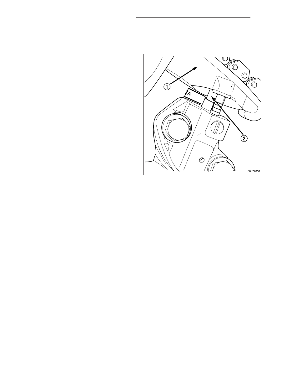
STANDARD PROCEDURE - MEASURING TIMING CHAIN WEAR

NOTE: This procedure must be performed with the
timing chain cover removed.

1. Remove the timing chain cover. (Refer to 9 -

ENGINE/VALVE TIMING/TIMING BELT / CHAIN
COVER(S) - REMOVAL).

2. To determine if the secondary timing chains are

worn, rotate the engine clockwise until maximum
tensioner piston (2) extension is obtained. Measure
the distance between the secondary timing chain
tensioner housing and the step ledge on the piston.
The measurement at point (A) must be less than
15mm (0.5906 inches).

3. If the measurement exceeds the specification the

secondary timing chains are worn and require
replacement. (Refer to 9 - ENGINE/VALVE TIM-
ING/TIMING BELT/CHAIN AND SPROCKETS -
REMOVAL).

NOTE: If the secondary chains are to be replaced
the primary chain must also be replaced.

STANDARD PROCEDURE - ENGINE TIMING - VERIFICATION

CAUTION: The 4.7L is a non free-wheeling design engine. Therefore, correct engine timing is critical.

NOTE: Components referred to as left hand or right hand are as viewed from the drivers position inside the
vehicle.

NOTE: The blue link plates on the chains and the dots on the camshaft drive sprockets may not line up
during the timing verification procedure. The blue link plates are lined up with the sprocket dots only when
re-timing the complete timing drive. Once the timing drive is rotated blue link-to-dot alignment is no longer
valid.

Engine base timing can be verified by the following procedure:

1. Remove the cylinder head covers (Refer to 9 - ENGINE/CYLINDER HEAD/CYLINDER HEAD COVER(S) -

REMOVAL).

9 - 994

ENGINE - 4.7L SERVICE INFORMATION

ND

2. Using a mirror, locate the TDC arrow on the front

cover. Rotate the crankshaft until the mark on the
crankshaft damper is aligned with the TDC arrow
on the front cover. The engine is now at TDC.

3. Note the location of the V8 mark stamped into the camshaft drive gears. If the V8 mark on each camshaft drive

gear is at the twelve o’clock position, the engine is at TDC (cylinder #1) on the exhaust stroke. If the V8 mark on
each gear is at the six o’clock position, the engine is at TDC (cylinder #1) on the compression stroke.

4. If both of the camshaft drive gears are off in the same or opposite directions, the primary chain or both second-

ary chains are at fault. Refer to Timing Chain and Sprockets procedure in this section.

5. If only one of the camshaft drive gears is off and the other is correct, the problem is confined to one secondary

chain. Refer to Single camshaft timing, in this procedure.

6. If both camshaft drive gear V8 marks are at the twelve o’clock or the six o’ clock position the engine base timing

is correct. Reinstall the cylinder head covers.

ND

ENGINE - 4.7L SERVICE INFORMATION

9 - 995

SINGLE CAMSHAFT TIMING

NOTE: to adjust the timing on one camshaft, peform the following procedure.

1. Using Chain Tensioner Wedge, special tool 8350 (3), stabilize the secondary chain drive. For reference purposes,

mark the chain-to-sprocket position.

2. Remove the camshaft drive gear retaining bolt.

3. Carefully remove the camshaft drive gear from the camshaft.

4. Re-index the camshaft drive gear in the chain until the V8 mark is at the same position as the V8 mark on the

opposite camshaft drive gear.

NOTE: When gripping the camshaft, place the pli-
ers on the tube portion of the camshaft only. Do
not grip the lobes or the sprocket areas.

5. Using a suitable pair of adjustable pliers (1), rotate

the camshaft until the alignment dowel (2) on the
camshaft is aligned with the slot in the camshaft
drive gear.

9 - 996

ENGINE - 4.7L SERVICE INFORMATION

ND

CAUTION:

Remove

excess

oil

from

camshaft

sprocket retaining bolt before reinstalling bolt.
Failure to do so may cause over-torqueing of bolt
resulting in bolt failure.

6. Position the camshaft drive gear onto the camshaft,

remove oil from bolt then install the retaining bolt.
Using Special Tools, Spanner Wrench 6958 with
Adapter Pins 8346 and a suitable torque wrench
(1), Tighten retaining bolt to 122N·m (90 ft. Lbs.).

ND

ENGINE - 4.7L SERVICE INFORMATION

9 - 997


Content   ..  862  863  864  865   ..