Dodge Dakota (ND). Manual - part 823


  Index      Dodge     Dodge Dakota (ND) 2005 - service repair manual 2005 year


Search            


Content   ..  821  822  823  824   ..


Dodge Dakota (ND). Manual - part 823


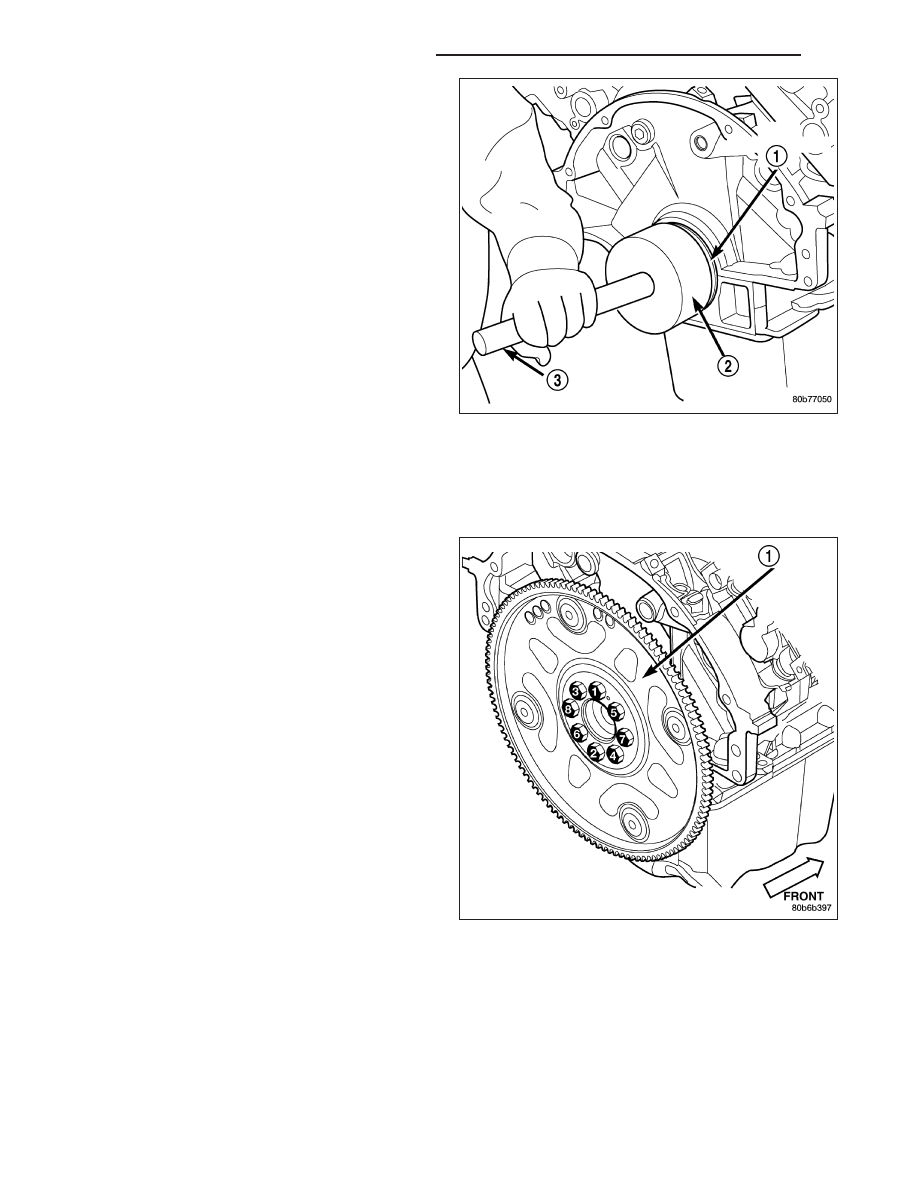
3. Using Special Tools 8349 Crankshaft Rear Oil Seal

Installer (2) and C-4171 Driver Handle (3), with a
hammer, tap the seal (1) into place. Continue to
tap on the driver handle until the seal installer
seats against the cylinder block crankshaft bore.

4. Install the flexplate (Refer to 9 - ENGINE/ENGINE

BLOCK/FLEX PLATE - INSTALLATION).

5. Install the transmission.

.

FLEX PLATE

REMOVAL

1. Remove the transmission. (Refer to 21 - TRANS-

MISSION/TRANSAXLE/AUTOMATIC

-

42RLE

-

REMOVAL).

2. Remove the bolts using the sequence provided.

3. Remove the flexplate.

9 - 830

ENGINE - 3.7L SERVICE INFORMATION

ND

INSTALLATION

1. Position the flexplate onto the crankshaft and install

the bolts hand tight.

2. Tighten the flexplate retaining bolts to 95 N·m (70

ft. lbs.) in the sequence shown.

3. Install the transmission. (Refer to 21 - TRANSMIS-

SION/TRANSAXLE/AUTOMATIC

-

42RLE

-

INSTALLATION).

ROD-PISTON & CONNECTING

DESCRIPTION

CAUTION: Do not use a metal stamp to mark con-
necting rods as damage may result, instead use
ink or a scratch awl.

The pistons (2) are made of a high strength aluminum
alloy. The connecting rods are made of forged pow-
dered metal, with a “fractured cap” design (1). A full
floating piston pin (3) is used to attach the piston to
the connecting rod.

ND

ENGINE - 3.7L SERVICE INFORMATION

9 - 831

STANDARD PROCEDURE

CONNECTING ROD BEARING FITTING

Inspect the connecting rod bearings for scoring (10
and (3). Check the bearings for normal wear patterns,
scoring, grooving, fatigue and pitting. Replace any
bearing that shows abnormal wear.

Inspect the connecting rod journals for signs of scor-
ing, nicks and burrs.

Misaligned or bent connecting rods can cause abnor-
mal wear on pistons, piston rings, cylinder walls, con-
necting rod bearings and crankshaft connecting rod
journals. If wear patterns or damage to any of these
components indicate the probability of a misaligned
connecting rod, inspect it for correct rod alignment.
Replace misaligned, bent or twisted connecting rods.

1. Wipe the oil from the connecting rod journal.

2. Lubricate the upper bearing insert (2) and position

in connecting rod (1). Center bearing insert in con-
necting rod

3. Measure at point A and point B. Measurement

should be less then .50mm (.0196 in.).

9 - 832

ENGINE - 3.7L SERVICE INFORMATION

ND

4. Use piston ring compressor (3) and Guide Pins

Special Tool 8507 (4) to install the rod and piston
assemblies. The oil slinger slots in the rods must
face front of the engine. The “F”’s (1) near the pis-
ton wrist pin bore should point to the front of the
engine.

5. Install the lower bearing insert in the bearing cap.

Center bearing insert in connecting rod. The lower
insert must be dry. Place strip of Plastigage (1)
across full width of the lower insert at the center of
bearing cap. Plastigage must not crumble in use. If
brittle, obtain fresh stock.

6. Install bearing cap and connecting rod on the jour-

nal and tighten bolts to 27 N·m (20 ft. lbs.) plus a
90° turn. DO NOT rotate crankshaft. Plastigage will
smear, resulting in inaccurate indication.

7. Remove the bearing cap and determine amount of

bearing-to-journal

clearance

by

measuring

the

width of compressed Plastigage (2). Refer to
Engine Specifications for the proper clearance.
Plastigage should indicate the same clearance
across the entire width of the insert. If the
clearance varies, it may be caused by either a
tapered journal, bent connecting rod or foreign
material trapped between the insert and cap or
rod.

8. If the correct clearance is indicated, replacement of

the bearing inserts is not necessary. Remove the
Plastigage from crankshaft journal and bearing insert. Proceed with installation.

ND

ENGINE - 3.7L SERVICE INFORMATION

9 - 833


Content   ..  821  822  823  824   ..