Dodge Dakota (ND). Manual - part 681


  Index      Dodge     Dodge Dakota (ND) 2005 - service repair manual 2005 year


Search            


Content   ..  679  680  681  682   ..


Dodge Dakota (ND). Manual - part 681


P0208-FUEL INJECTOR 8 CIRCUIT (CONTINUED)

5.

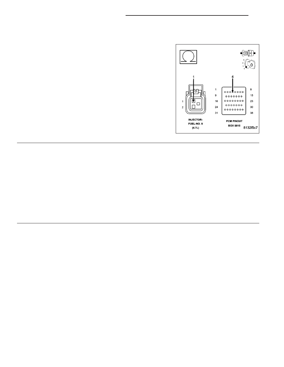
(K28) INJECTOR CONTROL NO.8 CIRCUIT OPEN

Turn the ignition off.

Disconnect the C1 PCM harness connector.

CAUTION: Do not probe the PCM harness connectors. Probing
the PCM harness connectors will damage the PCM terminals
resulting in poor terminal to pin connection. Install Miller Special
Tool #8815 to perform diagnosis.
Measure the resistance of the (K28) Injector Control No.8 circuit from
the Fuel Injector harness connector to the appropriate terminal of spe-
cial tool #8815.

Is the resistance below 5.0 ohms?

Yes

>> Go To 6

No

>> Repair the open in the (K28) Injector Control No.8 circuit.

Perform POWERTRAIN VERIFICATION TEST. (Refer to 9
- ENGINE - STANDARD PROCEDURE)

6.

PCM

NOTE: Before continuing, check the PCM harness connector terminals for corrosion, damage, or terminal
push out. Repair as necessary.
Using the schematics as a guide, inspect the wire harness and connectors. Pay particular attention to all Power and
Ground circuits.

Were there any problems found?

Yes

>> Repair as necessary.

Perform POWERTRAIN VERIFICATION TEST. (Refer to 9 - ENGINE - STANDARD PROCEDURE)

No

>> Replace and program the Powertrain Control Module per Service Information.

Perform POWERTRAIN VERIFICATION TEST. (Refer to 9 - ENGINE - STANDARD PROCEDURE)

9 - 262

ENGINE ELECTRICAL DIAGNOSTICS

ND

P0300-MULTIPLE CYLINDER MISFIRE

For the Engine circuit diagram (Refer to 9 - ENGINE - SCHEMATICS AND DIAGRAMS).

For a complete wiring diagram Refer to Section 8W.

When Monitored:
Any time the engine is running, and the adaptive numerator has been successfully updated.

Set Condition:
When more than a 2% (2.5% LEV) misfire rate is measured during two trips. Above 3000 RPM 1 trip less than
3000 RPM 2 trip. Three good trips to turn off the MIL.

Possible Causes

(A955) ASD RELAY OUTPUT CIRCUIT

INJECTOR CONTROL CIRCUIT

COIL CONTROL CIRCUIT

IGNITION WIRE

SPARK PLUG

IGNITION COIL

FUEL PUMP INLET STRAINER PLUGGED

RESTRICTED FUEL SUPPLY LINE

FUEL PUMP MODULE

FUEL PRESSURE LEAK DOWN

FUEL INJECTOR

ENGINE MECHANICAL PROBLEM

PCM

Always perform the Pre-Diagnostic Troubleshooting procedure before proceeding. (Refer to 9 - ENGINE -
DIAGNOSIS AND TESTING).

Diagnostic Test

1.

CYLINDER MIS-FIRE CONDITION ACTIVE

NOTE: Check for any TSB’s that apply to a Misfire condition. Review the vehicle repair history for any mis-
fire condition repairs that have been performed.
Star the engine.

Observe the WHICH CYLINDER IS MISFIRING screen for at least one minute on the scan tool.

Is there a misfire present?

Yes

>> Go To 2

No

>> Refer to the INTERMITTENT CONDITION Diagnostic Procedure.

Perform (NGC) POWERTRAIN VERIFICATION TEST. (Refer to 9 - ENGINE - STANDARD PROCE-
DURE)

ND

ENGINE ELECTRICAL DIAGNOSTICS

9 - 263

P0300-MULTIPLE CYLINDER MISFIRE (CONTINUED)

2.

VISUAL INSPECTION

NOTE: Anything that affects the speed of the crankshaft can cause a misfire DTC.

NOTE: When a Misfire is detected for a particular cylinder, the PCM will shut down that cylinders Injector
Control circuit.
- Visually inspect the engine for any of the following conditions.

- Worn serpentine belt

- Binding Engine-Driven accessories: A/C Compressor, P/S Pump, Water pump.

- Misalignment of the Water pump, P/S Pump and A/C Compressor pulleys

- Corroded PCM power and ground circuits.

- Improper CKP, CMP, MAP, and TP Sensor mounting

- Poor connector/terminal to component connection. i.e., CKP sensor, Fuel Injector, Ign coil, etc.

- Vacuum leaks

- Restricted Air Induction system or Exhaust system.

- Internal engine component failures.

Were any of the above conditions present?

Yes

>> Repair as necessary.

Perform

8

POWERTRAIN VERIFICATION TEST. (Refer to 9 - ENGINE - STANDARD PROCEDURE)

No

>> Go To 3

3.

(A955) ASD RELAY OUTPUT CIRCUIT

Turn the ignition off.

Disconnect the Ignition Coil harness connector of the misfiring cylinders.

Disconnect the Fuel Injector harness connector of the misfiring cylinders.

Ignition on, engine not running.

With a scan tool, actuate the ASD Relay.

Using a 12-volt test light connected to ground, probe the (A955) ASD Relay Output circuit in the Ignition Coil har-
ness connector and Fuel Injector harness connector while the relay is actuating.

Does the test light illuminate brightly?

Yes

>> Go To 4

No

>> Repair the excessive resistance or short to ground in the (A955) ASD Relay Output circuit.

Perform POWERTRAIN VERIFICATION TEST. (Refer to 9 - ENGINE - STANDARD PROCEDURE)

9 - 264

ENGINE ELECTRICAL DIAGNOSTICS

ND

P0300-MULTIPLE CYLINDER MISFIRE (CONTINUED)

4.

IGNITION SYSTEM OPERATION

Turn the ignition off.

Connect the Ignition Coil harness connectors.

Remove the Ignition Coils.

Leave the Fuel Injector harness connector of the cylinder being tested disconnected.

Install a spark tester on the Ignition Coil.

While cranking the engine observe the spark coming from the spark tester.

NOTE: A crisp blue spark that is able to jump the gap of the spark tester should be generated.

Is good spark present?

Yes

>> Go To 5

No

>> Go To 14

NOTE: Connect the Fuel Injector harness connector before continuing.

5.

SPARK PLUG

Turn the ignition off.

Remove the Spark Plug.

Inspect the Spark Plug for the following conditions.

- Cracks

- Carbon Tracking

- Foreign Material

- Gap size out of specifications

- Loose or broke electrode

NOTE: Lightly tap the bottom of the spark plug on a solid surface. The electrode in the spark plug should
not move.

Does the Spark Plug have any problems?

Yes

>> Replace the Spark Plug.

Perform POWERTRAIN VERIFICATION TEST. (Refer to 9 - ENGINE - STANDARD PROCEDURE)

No

>> Go To 6

6.

FUEL PRESSURE CHECK

WARNING: The fuel system is under a constant pressure (even with the engine off). Before testing or ser-
vicing any fuel system hose, fitting or line, the fuel system pressure must be released. Failure to follow
these instructions can result in personal injury or death.
Install a fuel pressure gauge to the fuel rail.

Start the engine and observe the fuel pressure reading.

NOTE: Fuel pressure specification is 407 KPa +/- 34 KPa (59 psi +/- 5 psi).

Choose a conclusion that best matches your fuel pressure reading.

Within Specification

Go To 7

Below Specification

Go To 12

Above Specification

Replace the fuel filter/pressure regulator.

Perform POWERTRAIN VERIFICATION TEST. (Refer to 9 - ENGINE - STANDARD PROCEDURE)

ND

ENGINE ELECTRICAL DIAGNOSTICS

9 - 265


Content   ..  679  680  681  682   ..