Dodge Dakota (ND). Manual - part 671
P0174-FUEL SYSTEM 2/1 LEAN (CONTINUED)
9.
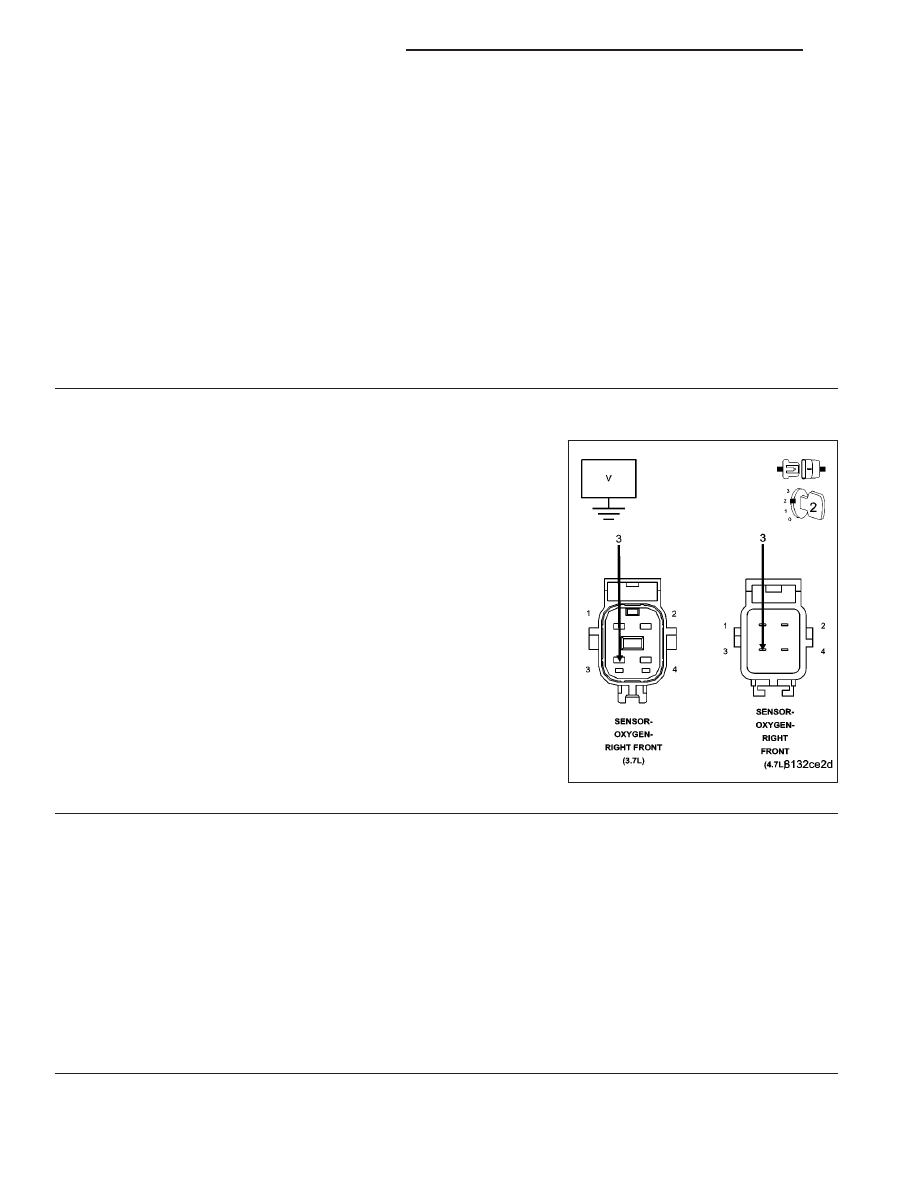
O2 SENSOR SIGNAL CIRCUIT
With the scan tool, monitor all the O2 Sensor voltage reading with the jumper wire removed.
NOTE: The scan tool will display all O2 Sensor voltage readings approximately 5.0 volts when only one O2
Sensor’s Signal circuit is shorted to voltage.
NOTE: The scan tool will display one O2 Sensor voltage close to zero and the others will read lower than
normal when one O2 Sensor Signal circuit contains excessive resistance.
Is the voltage above 4.8 volts?
Yes
>> Go To 10
No
>> Check all the O2 Signal circuits for a short to ground, open, or short to voltage. Inspect the O2 Sensor
connector and the PCM harness connector. If OK, replace and program the Powertrain Control Module
per Service Information.
Perform POWERTRAIN VERIFICATION TEST. (Refer to 9 - ENGINE - STANDARD PROCEDURE)
10.
(K902) O2 RETURN UPSTREAM CIRCUIT
Disconnect the 2/1 O2 Sensor harness connector.
Measure the voltage on the (K902) O2 Return Upstream circuit in the
O2 Sensor harness connector.
Is the voltage at 2.5 volts?
Yes
>> Go To 11
No
>> Check the (K902) O2 Return Upstream circuit for a short
to ground, open, or short to voltage. Inspect the O2 Sen-
sor connector and the PCM harness connector. If OK,
replace and program the Powertriain Control Module per
Service Information.
Perform POWERTRAIN VERIFICATION TEST. (Refer to 9
- ENGINE - STANDARD PROCEDURE)
11.
PCM
NOTE: Before continuing, check the PCM harness connector terminals for corrosion, damage, or terminal
push out. Repair as necessary.
Using the schematics as a guide, inspect the wire harness and connectors. Pay particular attention to all Power and
Ground circuits.
Were there any problems found?
Yes
>> Repair as necessary.
Perform POWERTRAIN VERIFICATION TEST. (Refer to 9 - ENGINE - STANDARD PROCEDURE)
No
>> Replace and program the Powertrain Control Module per Service Information.
Perform POWERTRAIN VERIFICATION TEST. (Refer to 9 - ENGINE - STANDARD PROCEDURE)
9 - 222
ENGINE ELECTRICAL DIAGNOSTICS
ND