Dodge Dakota (ND). Manual - part 653


  Index      Dodge     Dodge Dakota (ND) 2005 - service repair manual 2005 year


Search            


Content   ..  651  652  653  654   ..


Dodge Dakota (ND). Manual - part 653


P0135-O2 SENSOR 1/1 HEATER PERFORMANCE (CONTINUED)

2.

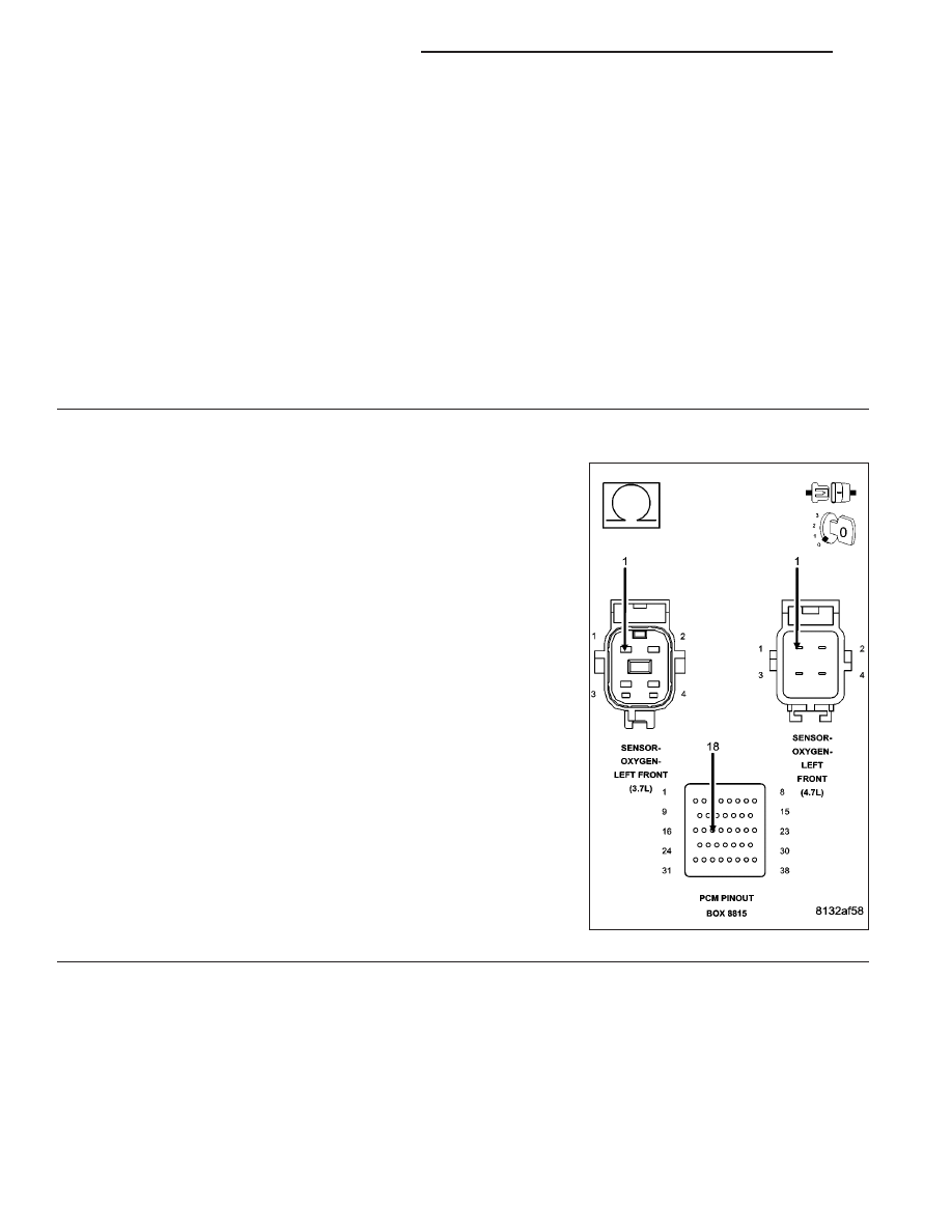
O2 SENSOR HEATER ELEMENT

Turn the ignition off.

NOTE: Allow the O2 sensor to cool down to room temperature.
Disconnect the O2 Sensor harness connector.

Measure the resistance of the O2 Heater Element across the 1/1 O2 Sensor connector between the O2 Heater
Control terminal and the Heater ground terminal.

NOTE: O2 Heater Element resistance values should be measured at 70°F (21.1°C). The resistance value will
vary with different temperature values.

Is the resistance of the O2 Sensor Heater Element between 2.0 and 30.0 ohms?

Yes

>> Go To 3

No

>> Replace the O2 Sensor.

Perform POWERTRAIN VERIFICATION TEST. (Refer to 9 - ENGINE - STANDARD PROCEDURE)

3.

(K99) O2 1/1 HEATER CONTROL CIRCUIT OPEN

Disconnect the C2 PCM harness connector.

CAUTION: Do not probe the PCM harness connectors. Probing
the PCM harness connectors will damage the PCM terminals
resulting in poor terminal to pin connection. Install Miller Special
Tool #8815 to perform diagnosis.
Measure the resistance of the (K99) O2 1/1 Heater Control circuit from
the O2 harness connector to the appropriate terminal of special tool
#8815.

Is the resistance below 0.5 of an ohm?

Yes

>> Go To 4

No

>> Repair the excessive resistance in the (K99) O2 1/1

Heater Control circuit.

Perform POWERTRAIN VERIFICATION TEST. (Refer to 9
- ENGINE - STANDARD PROCEDURE)

9 - 150

ENGINE ELECTRICAL DIAGNOSTICS

ND

P0135-O2 SENSOR 1/1 HEATER PERFORMANCE (CONTINUED)

4.

(Z43) O2 1/1 HEATER GROUND CIRCUIT OPEN

Measure the resistance between ground and the (Z43) O2 1/1Heater
ground circuit in the O2 Sensor harness connector.

Is the resistance below 0.5 of an ohm?

Yes

>> Go To 5

No

>> Repair the excessive resistance in the (Z43) O2 1/1

Heater ground circuit.

Perform POWERTRAIN VERIFICATION TEST. (Refer to 9
- ENGINE - STANDARD PROCEDURE)

5.

PCM

NOTE: Before continuing, check the PCM harness connector terminals for corrosion, damage, or terminal
push out. Repair as necessary.
Using the schematics as a guide, inspect the wire harness and connectors. Pay particular attention to all Power and
Ground circuits.

Were there any problems found?

Yes

>> Repair as necessary.

Perform POWERTRAIN VERIFICATION TEST. (Refer to 9 - ENGINE - STANDARD PROCEDURE)

No

>> Replace and program the Powertrain Control Module per Service Information.

Perform POWERTRAIN VERIFICATION TEST. (Refer to 9 - ENGINE - STANDARD PROCEDURE)

ND

ENGINE ELECTRICAL DIAGNOSTICS

9 - 151

P0137-O2 SENSOR 1/2 CIRCUIT LOW

9 - 152

ENGINE ELECTRICAL DIAGNOSTICS

ND

P0137-O2 SENSOR 1/2 CIRCUIT LOW (CONTINUED)

For the Engine circuit diagram (Refer to 9 - ENGINE - SCHEMATICS AND DIAGRAMS).

For a complete wiring diagram Refer to Section 8W.

When Monitored:
Engine running for less than 30 seconds and the O2 Sensor Heater Temperature is less than 251°C (484°F)
with battery voltage greater 10.99 volts.

Set Condition:
The oxygen sensor signal voltage is below 2.5196 volts for 3 seconds after starting engine. One Trip Fault.
Three good trips to turn off the MIL.

Possible Causes

(K904) O2 RETURN DOWNSTREAM CIRCUIT SHORTED TO GROUND

(K141) O2 1/2 SIGNAL CIRCUIT SHORTED TO GROUND

(K141) O2 1/2 SIGNAL CIRCUIT SHORTED TO THE (K904) O2 RETURN DOWNSTREAM CIRCUIT

(K141) O2 1/2 SIGNAL CIRCUIT SHORTED TO THE (Z42) O2 1/2 HEATER GROUND CIRCUIT

O2 SENSOR

PCM

Always perform the Pre-Diagnostic Troubleshooting procedure before proceeding. (Refer to 9 - ENGINE -
DIAGNOSIS AND TESTING).

Diagnostic Test

1.

O2 SENSOR BELOW 2.52 VOLTS

Start the engine.

Allow the engine to reach normal operating temperature.

With a scan tool, read the 1/2 O2 Sensor voltage.

Is the voltage below 2.52 volts?

Yes

>> Go To 2

No

>> Refer to the INTERMITTENT CONDITION Diagnostic Procedure.

Perform POWERTRAIN VERIFICATION TEST. (Refer to 9 - ENGINE - STANDARD PROCEDURE)

2.

(K141) O2 1/2 SIGNAL CIRCUIT

Turn the ignition off.

Disconnect the 1/2 O2 Sensor harness connector.

Ignition on, engine not running.

With a scan tool, monitor the 1/2 O2 Sensor voltage.

Is the O2 Sensor voltage above 4.8 volts?

Yes

>> Go To 3

No

>> Go To 5

ND

ENGINE ELECTRICAL DIAGNOSTICS

9 - 153


Content   ..  651  652  653  654   ..