Dodge Dakota (ND). Manual - part 1259


  Index      Dodge     Dodge Dakota (ND) 2005 - service repair manual 2005 year


Search            


Content   ..  1257  1258  1259  1260   ..


Dodge Dakota (ND). Manual - part 1259


B105F–CLIMATE CONTROL MOTOR(S) COMMON 1 CONTROL CIRCUIT LOW (CONTINUED)

6.

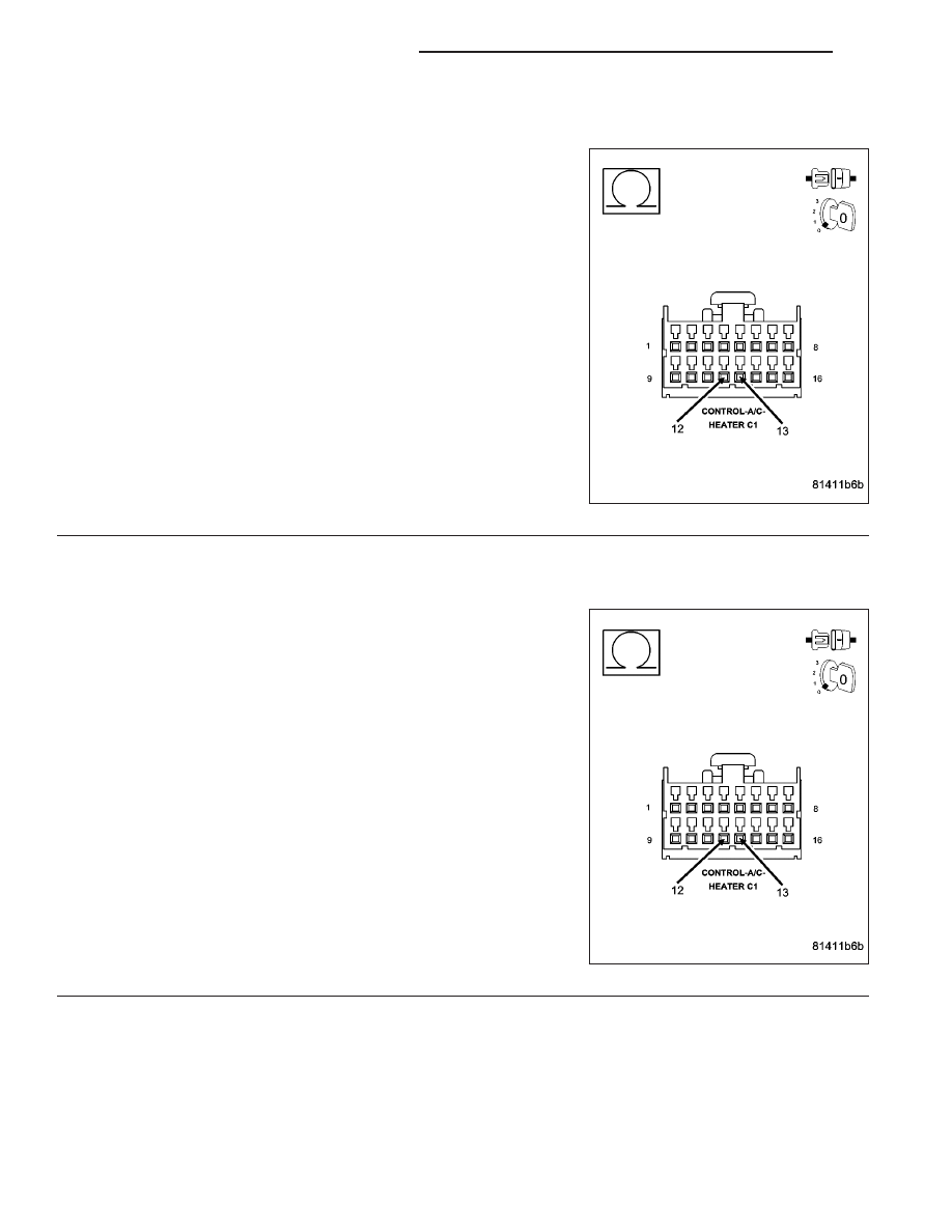
CHECK MODE DOOR 2 (FLOOR TO DEFROST) ACTUATOR CIRCUIT RESISTANCE

Measure the resistance between the (C801) Mode Door 2 Driver cir-
cuit and the (C34) Common Door Driver circuit in the A/C Heater Con-
trol C1 harness connector.

Is the resistance below 20 ohms?

Yes

>> Go To 7

No

>> Go To 8

7.

CHECK (C801) MODE DOOR 2 DRIVER CIRCUIT FOR A SHORT TO (C34) COMMON DOOR DRIVER
CIRCUIT

Disconnect the Mode Door 2 (Floor to Defrost) Actuator harness con-
nector.

Measure the resistance between the (C801) Mode Door 2 Driver cir-
cuit and the (C34) Common Door Driver circuit in the A/C Heater Con-
trol C1 harness connector.

Is the resistance below 10k ohms?

Yes

>> Repair the (C801) Mode Door 2 Driver Circuit for a short

to the (C34) Common Door Driver circuit.

Perform BODY VERIFICATION TEST - VER 1. (Refer to 8
-

ELECTRICAL/ELECTRONIC

CONTROL

MODULES/

FRONT CONTROL MODULE - DIAGNOSIS AND TEST-
ING).

No

>> Replace the Mode Door 2 (Floor to Defrost) Actuator in

accordance with the Service Information.

Perform BODY VERIFICATION TEST - VER 1. (Refer to 8
-

ELECTRICAL/ELECTRONIC

CONTROL

MODULES/

FRONT

CONTROL

MODULE

-

DIAGNOSIS

AND

TESTING).

24 - 34

HVAC - ELECTRICAL DIAGNOSTICS

ND

B105F–CLIMATE CONTROL MOTOR(S) COMMON 1 CONTROL CIRCUIT LOW (CONTINUED)

8.

CHECK RECIRCULATION DOOR ACTUATOR CIRCUIT RESISTANCE

Measure the resistance between the (C32) Recirculation Door Driver
circuit and the (C34) Common Door Driver circuit in the A/C Heater
Control C1 harness connector.

Is the resistance below 20 ohms?

Yes

>> Go To 9

No

>> Go To 10

9.

CHECK (C32) RECIRCULATION DOOR DRIVER CIRCUIT FOR A SHORT TO (C34) COMMON DOOR
DRIVER CIRCUIT

Disconnect the Recirculation Door Actuator harness connector.

Measure the resistance between the (C32) Recirculation Door Driver
circuit and the (C34) Common Door Driver circuit in the A/C Heater
Control C1 harness connector.

Is the resistance below 10k ohms?

Yes

>> Repair the (C32) Recirculation Door Driver circuit for a

short to the (C34) Common Door Driver circuit.

Perform BODY VERIFICATION TEST - VER 1. (Refer to 8
-

ELECTRICAL/ELECTRONIC

CONTROL

MODULES/

FRONT CONTROL MODULE - DIAGNOSIS AND TEST-
ING).

No

>> Replace the Recirculation Door Actuator in accordance

with the Service Information.

Perform BODY VERIFICATION TEST - VER 1. (Refer to 8
-

ELECTRICAL/ELECTRONIC

CONTROL

MODULES/

FRONT

CONTROL

MODULE

-

DIAGNOSIS

AND

TESTING).

ND

HVAC - ELECTRICAL DIAGNOSTICS

24 - 35

B105F–CLIMATE CONTROL MOTOR(S) COMMON 1 CONTROL CIRCUIT LOW (CONTINUED)

10.

RUN THE ACTUATOR DTC DETECTION TEST

Reconnect the A/C Heater Control C1 harness connector.

Turn the ignition on.

With the scan tool in HVAC, select System Tests and then select Actuator DTC Detection. When the test is com-
plete, select View DTCs.

Does the scan tool only display: B105F–CLIMATE CONTROL MOTOR(S) COMMON 1 CONTROL CIRCUIT
LOW?

Yes

>> Replace the A/C Heater Control in accordance with the Service Information.

Perform BODY VERIFICATION TEST - VER 1. (Refer to 8 - ELECTRICAL/ELECTRONIC CONTROL
MODULES/FRONT CONTROL MODULE - DIAGNOSIS AND TESTING).

No, Other DTC(s) Displayed

Diagnose and repair the other DTC(s). If multiple DTCs are present, beginning with the common circuit,
diagnose and repair all short high DTCs and then all short low DTCs. Refer to the Table of Contents in
this Section for a complete list of all HVAC related symptoms.

No, And No DTCs Displayed

Using the wiring diagram as a guide, inspect the wiring and connectors for conditions causing an inter-
mittent short. Repair as necessary.

Perform BODY VERIFICATION TEST - VER 1. (Refer to 8 - ELECTRICAL/ELECTRONIC CONTROL
MODULES/FRONT CONTROL MODULE - DIAGNOSIS AND TESTING).

24 - 36

HVAC - ELECTRICAL DIAGNOSTICS

ND

B1001–A/C SWITCH REQUEST INPUT CIRCUIT LOW

For a complete wiring diagram Refer to Section 8W.

Theory of Operation

The switch input changes when the switch is pushed down. A stored DTC B1001 indicates that the A/C mode switch
was stuck in a pushed position for more than two minutes, but has since returned to its normal state. An active DTC
B1001 indicates that the A/C mode switch is stuck in a pushed position. An active DTC B1001 will also prevent
proper switch and status indicator function as evidenced by not being able to turn the A/C status indicator either on
if off or off if on.

When Monitored:
With the ignition on.

Set Condition:
If the A/C mode switch stays in a pushed position for more than two minutes. This DTC has a maturing time
of two minutes and a de-maturing time of two seconds. If the DTC’s status changes from active to stored it will
stay in memory for 100 ignition cycles.

Possible Causes

A/C HEATER CONTROL DAMAGED

OBJECT HOLDING A/C MODE SWITCH IN A PUSHED POSITION

SUBSTANCE CAUSING A/C MODE SWITCH TO GET STUCK IN A PUSHED POSITION

A/C HEATER CONTROL

Diagnostic Test

1.

INSPECT THE A/C HEATER CONTROL FOR DAMAGE

Inspect the A/C Heater Control for damage.

Is the A/C Heater Control damaged?

Yes

>> Replace the A/C Heater Control in accordance with the Service Information.

Perform BODY VERIFICATION TEST – VER 1. (Refer to 8 - ELECTRICAL/ELECTRONIC CONTROL
MODULES/FRONT CONTROL MODULE - DIAGNOSIS AND TESTING).

No

>> Go To 2

2.

INSPECT FOR OBJECT OR SUBSTANCE CAUSING THE A/C MODE SWITCH TO STAY OR STICK IN A
PUSHED POSITION

Inspect the A/C Heater Control for anything that would cause the A/C mode switch to stay or stick in a pushed
position.

Is anything present that would cause the A/C mode switch to stay or stick in a pushed position?

Yes

>> Repair as necessary.

Perform BODY VERIFICATION TEST – VER 1. (Refer to 8 - ELECTRICAL/ELECTRONIC CONTROL
MODULES/FRONT CONTROL MODULE - DIAGNOSIS AND TESTING).

No

>> Go To 3

ND

HVAC - ELECTRICAL DIAGNOSTICS

24 - 37


Content   ..  1257  1258  1259  1260   ..