Dodge Dakota (ND). Manual - part 1089


  Index      Dodge     Dodge Dakota (ND) 2005 - service repair manual 2005 year


Search            


Content   ..  1087  1088  1089  1090   ..


Dodge Dakota (ND). Manual - part 1089


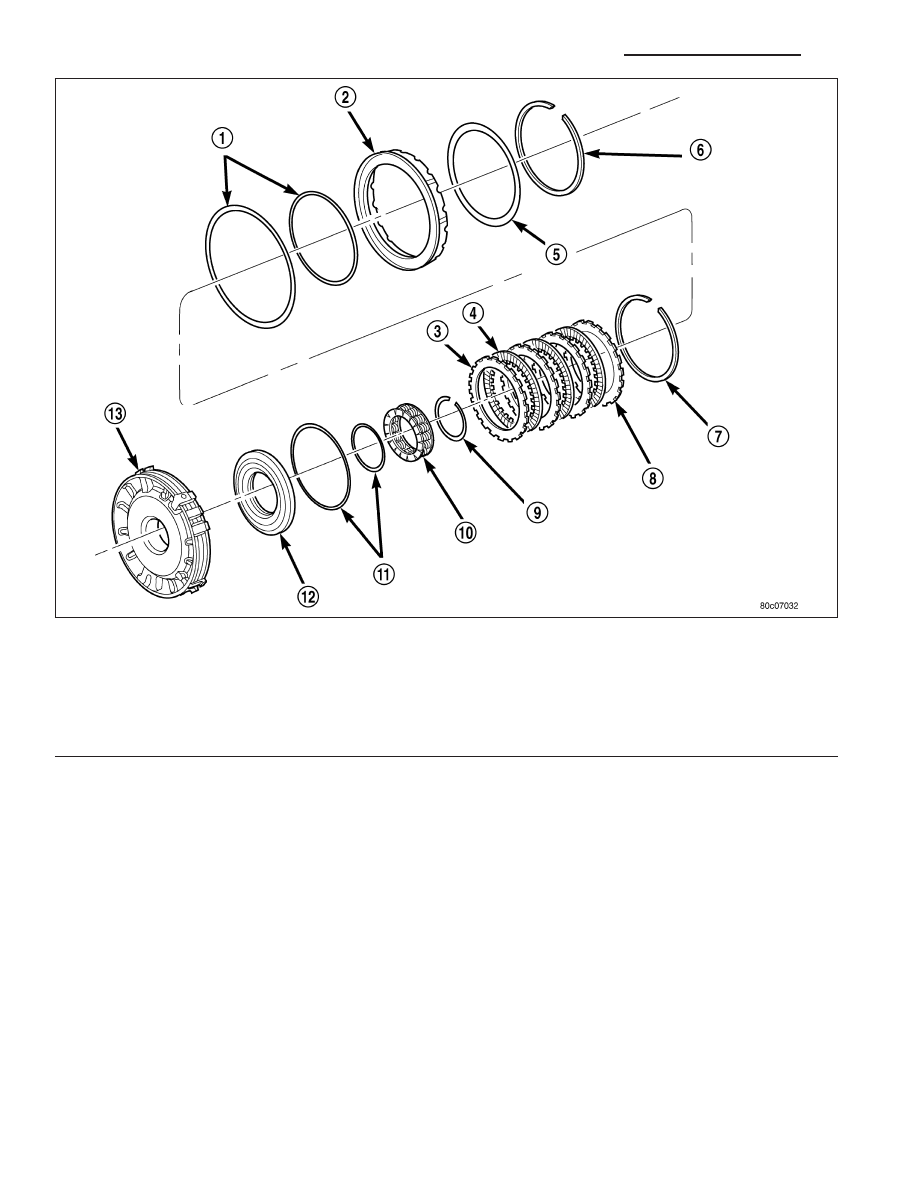
6. Assemble and install the 4C clutch pack (3, 4) into the retainer/bulkhead (13) with the steel separator plate

against the piston.

7. Install the 4C reaction plate (8) and snap-ring (7) into the retainer/bulkhead (13). The 4C reaction plate is non-

directional.

8. Measure the 4C clutch clearance. The correct clutch clearance is 0.77-1.39 mm (0.030-0.055 in.). The snap-ring

(7) is selectable. Install the chosen snap-ring and re-measure to verify the selection.

9. Install the 2C piston (2) into the retainer/bulkhead (13).

10. Position the 2C Belleville spring (5) onto the 2C piston (2).

11. Position the 2C Belleville spring snap-ring (6) onto the 2C Belleville spring (5).

4C Retainer/Bulkhead Components

1 - SEAL

8 - REACTION PLATE

2 - 2C PISTON

9 - SNAP-RING

3 - PLATE

10 - RETURN SPRING

4 - DISC

11 - SEAL

5 - 2C BELLEVILLE SPRING

12 - 4C PISTON

6 - SNAP-RING

13 - 4C RETAINER/BULKHEAD

7 - SNAP-RING (SELECT)

21 - 748

AUTOMATIC TRANSMISSION 545RFE - SERVICE INFORMATION

ND

12. Using Spring Compressor 8249 (2) and a suitable

shop press (1), compress the Belleville spring (5)
until the snap-ring (6) is engaged with the snap-
ring groove in the retainer/bulkhead.

SEAL-ADAPTER HOUSING

REMOVAL

1. Remove the transfer case from the transmission.

2. Using a screw mounted on a slide hammer, remove the adapter housing seal.

INSTALLATION

1. Clean the adapter seal bore in the adapter housing

of any residue or particles remaining from the orig-
inal seal.

2. Install new oil seal in the adapter housing using

Seal Installer C-3860-A (1). A properly installed
seal is flush to the face of the seal bore.

3. Install the transfer case onto the transmission.

ND

AUTOMATIC TRANSMISSION 545RFE - SERVICE INFORMATION

21 - 749

SYSTEM-BRAKE TRANSMISSION SHIFT INTERLOCK

DESCRIPTION

The Brake Transmission Shifter Interlock (BTSI), is a
solenoid operated system. It consists of a solenoid
permanently mounted on the gearshift cable.

OPERATION

The system locks the shifter into the PARK position. The interlock system is engaged whenever the ignition switch
is in the LOCK or ACCESSORY position. An additional electrically activated feature will prevent shifting out of the
PARK position unless the brake pedal is depressed approximately one-half an inch. A magnetic holding device in
line with the park lock cable is energized when the ignition is in the RUN position. When the key is in the RUN
position and the brake pedal is depressed, the shifter is unlocked and will move into any position. The interlock
system also prevents the ignition switch from being turned to the LOCK or ACCESSORY position, unless the shifter
is fully locked into the PARK position.

DIAGNOSIS AND TESTING - BRAKE TRANSMISSION SHIFT INTERLOCK

1. Verify that the key can only be removed in the PARK position.

2. When the shift lever is in PARK And the shift handle pushbutton is in the “OUT” position, the ignition key cylinder

should rotate freely from OFF to LOCK. When the shifter is in any other gear or neutral position, the ignition key
cylinder should not rotate to the LOCK position.

3. Shifting out of PARK should not be possible when the ignition key cylinder is in the OFF position.

4. Shifting out of PARK should not be possible while applying normal pushbutton force and ignition key cylinder is

in the RUN or START positions unless the foot brake pedal is depressed approximately 1/2 inch (12mm).

5. Shifting out of PARK should not be possible when the ignition key cylinder is in the ACCESSORY or LOCK

positions.

6. Shifting between any gears, NEUTRAL or into PARK may be done without depressing foot brake pedal with

ignition switch in RUN or START positions.

ADJUSTMENTS - BRAKE TRANSMISSION SHIFT INTERLOCK

Correct cable adjustment is important to proper interlock operation. The gearshift cable must be correctly adjusted
in order to shift out of PARK.

21 - 750

AUTOMATIC TRANSMISSION 545RFE - SERVICE INFORMATION

ND

ADJUSTMENT PROCEDURE

1. Remove the steering column trim as necessary for

access to the brake transmission shift interlock.

2. Shift the transmission into the PARK position.

3. Pull upward on both the BTSI lock tab (4) and the

gearshift cable lock tab (3).

4. Verify that the shift lever is in the PARK position.

5. Verify positive engagement of the transmission

park lock by attempting to rotate the propeller
shaft. The shaft will not rotate when the park lock is
engaged.

6. Turn ignition switch to LOCK position. Be sure

ignition key cylinder is in the LOCK position.
Cable will not adjust correctly in any other
position.

7. Ensure that the cable is free to self-adjust by push-

ing cable rearward and releasing.

8. Push the gearshift cable lock tab (3) down until it snaps in place.

9. Locate the BTSI alignment hole in the bottom of the BTSI mechanism between the BTSI lock tab and the BTSI

connector.

10. Move the BTSI assembly up or down on the gearshift cable until an appropriate size drill bit can be inserted into

the alignment hole and through the assembly.

11. Push the BTSI lock tab (4) down until it snaps into place and remove the drill bit.

12. Install any steering column trim previously removed.

BTSI FUNCTION CHECK

1. Verify removal of ignition key allowed in PARK position only.

2. When the shift lever is in PARK, the ignition key cylinder should rotate freely from off to lock. When the shifter

is in any other position, the ignition key should not rotate from off to lock.

3. Shifting out of PARK should be possible when the ignition key cylinder is in the off position.

4. Shifting out of PARK should not be possible while applying normal force, and ignition key cylinder is in the run

or start positions, unless the foot brake pedal is depressed approximately 1/2 inch (12mm).

5. Shifting out of PARK should not be possible when the ignition key cylinder is in the accessory or lock position.

6. Shifting between any gear and NEUTRAL, or PARK, may be done without depressing foot brake with ignition

switch in run or start positions.

7. Engine starts must be possible with shifter lever in PARK or NEUTRAL positions only. Engine starts must not be

possible in any position other than PARK or NEUTRAL.

8. With shifter lever in the:

PARK position - Apply upward force on the shift arm and remove pressure. Engine starts must be possible.

PARK position - Apply downward force on the shift arm and remove pressure. Engine starts must be possible.

NEUTRAL position - Normal position. Engine starts must be possible.

NEUTRAL position - Engine running and brakes applied, apply upward force on the shift arm. Transmission
shall not be able to shift from neutral to reverse.

ND

AUTOMATIC TRANSMISSION 545RFE - SERVICE INFORMATION

21 - 751


Content   ..  1087  1088  1089  1090   ..