Index Dodge Dodge Dakota (ND) 2005 - service repair manual 2005 year
Search
Content .. 84 85 86 87 ..
Dodge Dakota (ND). Manual - part 86
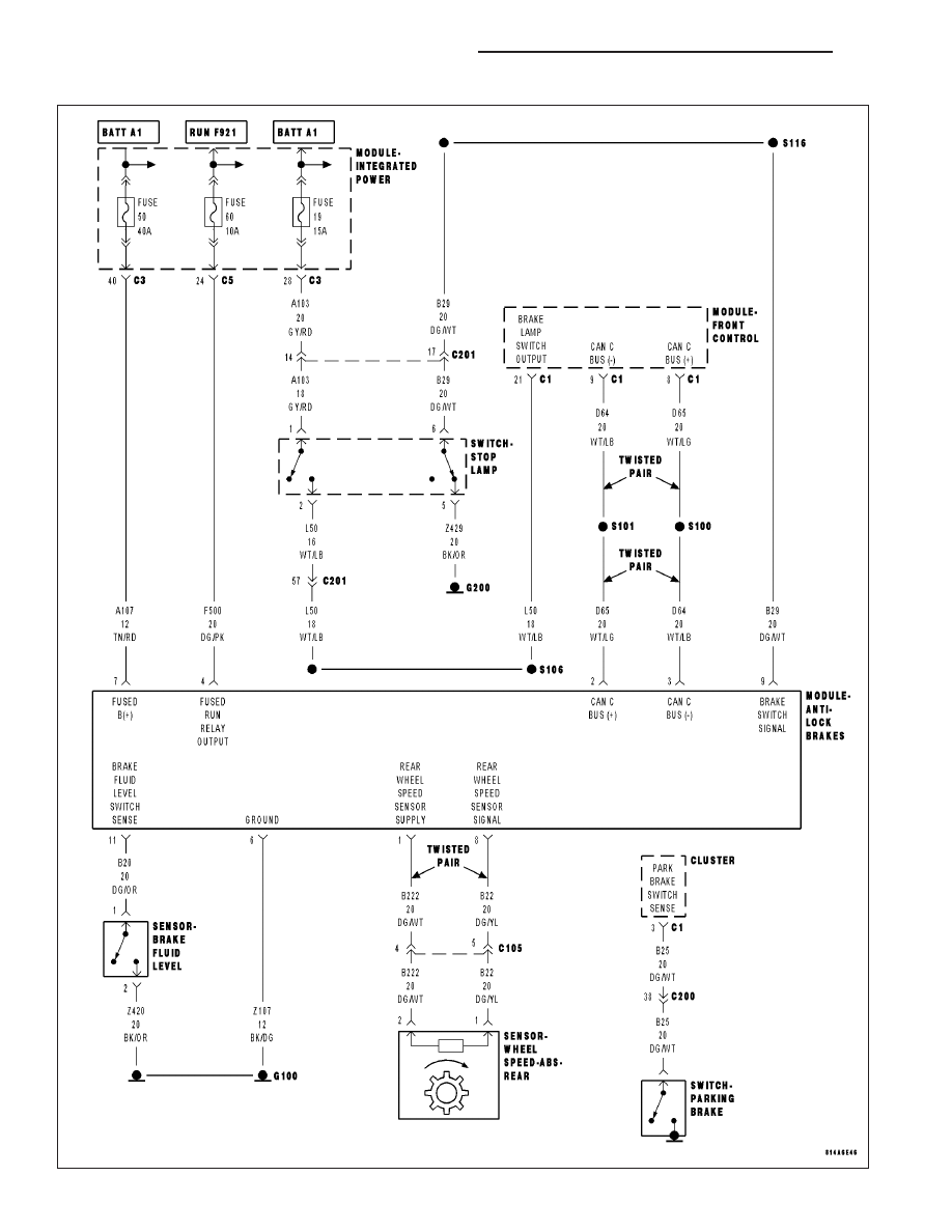
U1003–ESP CAN C BUS PERFORMANCE (EBC125)
5 - 114
BRAKES - ABS ELECTRICAL DIAGNOSTICS
ND