Dodge Dakota (ND). Manual - part 35


  Index      Dodge     Dodge Dakota (ND) 2005 - service repair manual 2005 year


Search            


Content   ..  33  34  35  36   ..


Dodge Dakota (ND). Manual - part 35


6. Hold companion flange with Holder 6719 and four

bolts and washers.

7. Remove pinion nut.

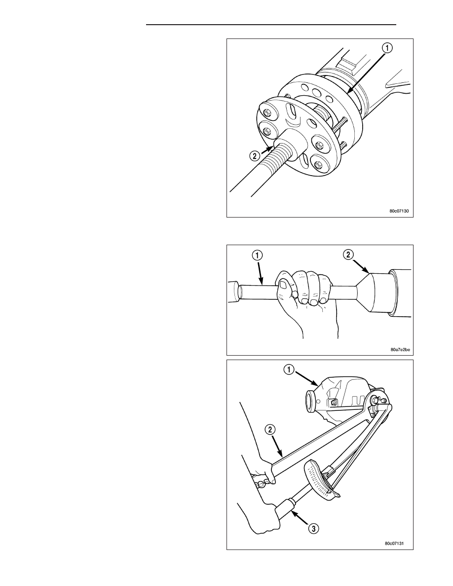
8. Remove companion flange (1) with Remover C-452

(2).

9. Remove pinion seal with a seal pick.

INSTALLATION

1. Apply a light coating of gear lubricant on the lip of

pinion seal.

2. Install seal with Installer C-3972-A (2) and Handle

C-4171 (1).

3. Install companion flange onto the pinion with

Installer C-3718 and holder.

4. Hold companion flange with Holder 6719A (2).

5. Install new pinion nut and tighten nut until there is

zero bearing end-play.

CAUTION: Do not exceed minimum tightening
torque when installing companion flange at this
point. Failure to follow these instructions will dam-
age the collapsible spacer or bearings.

6. Tighten pinion nut to 271 N·m (200 ft. lbs.).

3 - 56

FRONT AXLE - C205F

ND

CAUTION: Never loosen pinion nut to decrease
pinion bearing rotating torque and never exceed
specified preload torque. If preload torque or rotat-
ing torque is exceeded a new collapsible spacer
must be installed.

7. Record pinion (1) rotating torque, with a torque

wrench (2). Rotating torque should be equal to the
reading recorded during removal plus an additional
0.56 N·m (5 in. lbs.).

8. If rotating torque is low, tighten pinion nut in 6.8

N·m (5 ft. lbs.) increments until rotating torque is
achieved.

NOTE: If maximum tightening torque is reached
prior to reaching the required rotating torque, the
collapsible

spacer

may

have

been

damaged.

Replace the collapsible spacer.

9. Install propeller shaft with reference marks aligned.

10. Install half shafts.

11. Add gear lubricant to differential housing if necessary.

DIFFERENTIAL

REMOVAL

1. Remove differential housing cover and drain fluid.

2. Remove axle shafts.

3. Loosen bearing cap bolts.

NOTE: Differential bearing cap reference numbers
are stamped on caps and machined flat on the
housing. If reference numbers cannot be found,
make new marks for later reference.

4. Install Adapter Plates 8142-A (1) onto the housing.

5. Install Spreader W-129-B (2) onto the adapter

plates and tighten the turnbuckle finger-tight.

ND

FRONT AXLE - C205F

3 - 57

6. Install a Pilot Stud L-4438 at the left side of the dif-

ferential housing. Attach Dial Indicator C-3339 (1)
to pilot stud. Load the indicator plunger against the
opposite side of the housing and zero the indicator.

7. Spread the housing to remove the differential case

from the housing. Measure the distance with the
dial indicator.

CAUTION: Never spread over 0.50 mm (0.020 in).
Failure to follow these instructions will damage
the housing.

8. Remove dial indicator.

9. While holding the differential case in position,

remove bearing cap bolts and caps.

10. Remove differential (2) from the housing (1).

Ensure differential bearing cups and shims remain
in position on the differential bearings.

11. Tag differential bearing cups and shims to indicate

their location.

12. Remove spreader from housing.

3 - 58

FRONT AXLE - C205F

ND

DISASSEMBLY

1. Rotate one pinion gear (2) with thrust washer (3) to

the differential window (1) and remove gear and
thrust washer.

2. Rotate remaining pinion gear (3) with thrust washer

(2) to the differential window (1) and remove gear
and washer.

3. Remove differential side gears (1) (2) and thrust

washers.

ND

FRONT AXLE - C205F

3 - 59


Content   ..  33  34  35  36   ..