Dodge Dakota (ND). Manual - part 31


  Index      Dodge     Dodge Dakota (ND) 2005 - service repair manual 2005 year


Search            


Content   ..  29  30  31  32   ..


Dodge Dakota (ND). Manual - part 31


If installing a new gear, note the depth variance number of the original and replacement pinion. Add or subtract this
number from the original depth shim/oil slinger to compensate for the difference in the depth variances. The num-
bers represent thousands of an inch deviation from the standard. If the number is negative, add that value to the
required thickness of the depth shims. If the number is positive, subtract that value from the thickness of the depth
shim.

Pinion Gear Depth Variance Chart: Note where Old and New Pinion Marking columns intersect. Intersecting figure
represents plus or minus the amount needed.

PINION GEAR DEPTH VARIANCE

New Pinion Gear Depth Variance

Original Pinion

Gear Depth

Variance

2

4

2

3

2

2

2

1

0

+1

+2

+3

+4

+4

+0.008

+0.007

+0.006

+0.005

+0.004

+0.003

+0.002

+0.001

0

+3

+0.007

+0.006

+0.005

+0.004

+0.003

+0.002

+0.001

0

2

0.001

+2

+0.006

+0.005

+0.004

+0.003

+0.002

+0.001

0

2

0.001

2

0.002

+1

+0.005

+0.004

+0.003

+0.002

+0.001

0

2

0.001

2

0.002

2

0.003

0

+0.004

+0.003

+0.002

+0.001

0

2

0.001

2

0.002

2

0.003

2

0.004

2

1

+0.003

+0.002

+0.001

0

2

0.001

2

0.002

2

0.003

2

0.004

2

0.005

2

2

+0.002

+0.001

0

2

0.001

2

0.002

2

0.003

2

0.004

2

0.005

2

0.006

2

3

+0.001

0

2

0.001

2

0.002

2

0.003

2

0.004

2

0.005

2

0.006

2

0.007

2

4

0

2

0.001

2

0.002

2

0.003

2

0.004

2

0.005

2

0.006

2

0.007

2

0.008

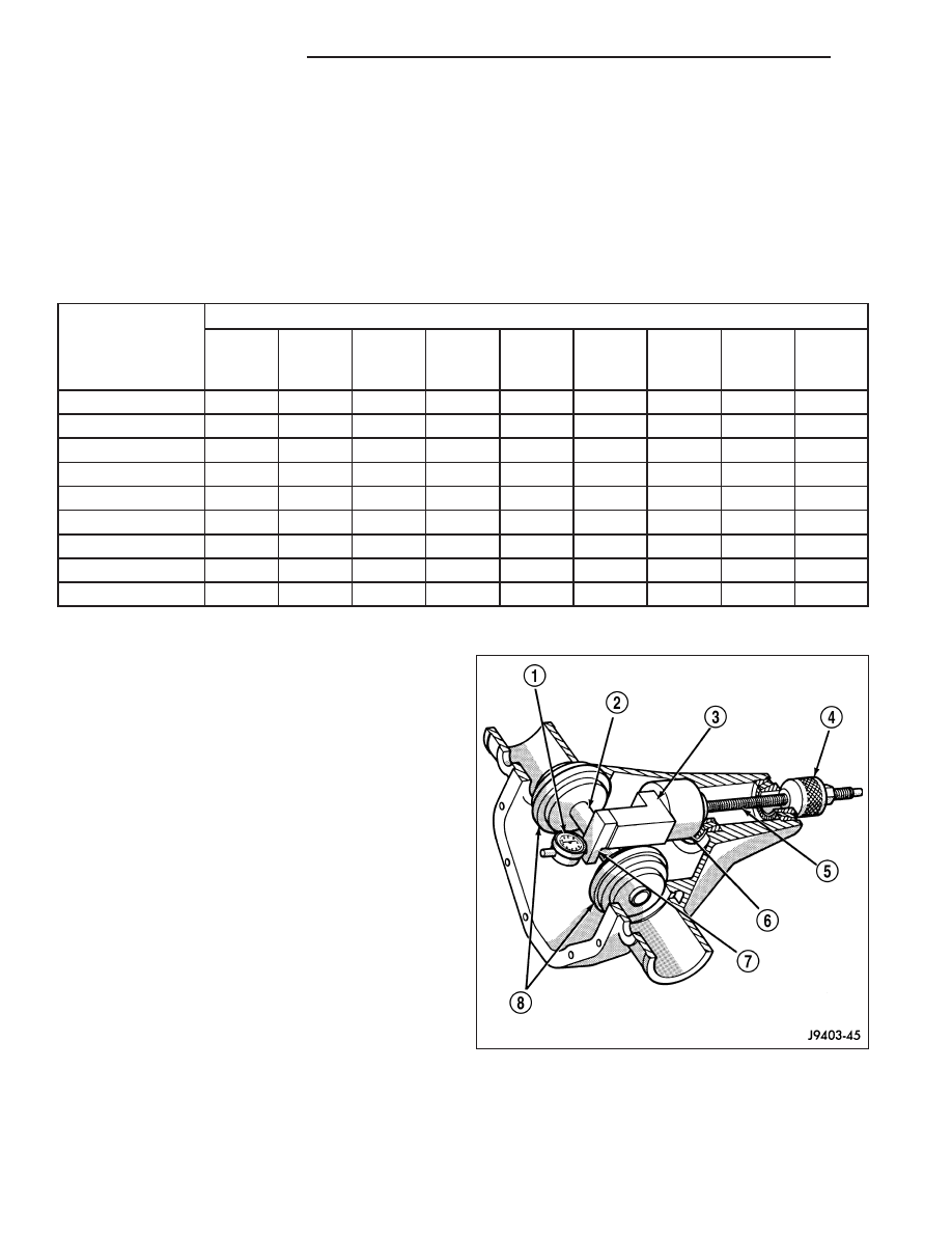
PINION DEPTH MEASUREMENT

Measurements are taken with pinion cups and pinion
bearings installed in housing. Take measurements with
a Pinion Gauge Set, Pinion Block 8177 (6), Arbor
Discs 8541(8) and Dial Indicator C-3339 (1).

1. Assemble Pinion Height Block 6739 (3), Pinion

Block 8177 (6) and rear pinion bearing onto Screw
6741 (5).

3 - 40

FRONT AXLE - C205F

ND

2. Insert assembled height gauge components (1) (2),

rear bearing and screw into the housing through
the pinion bearing cups.

3. Install front pinion bearing and Cone-Nut 6740 onto

the screw. Tighten cone-nut until Torque To Rotate
the screw is 2.0 N·m (18 in. lbs.).

4. Place Arbor Discs 8541 (1) on Arbor D-115-3 (3) in

position in the housing side bearing cradles. Install
differential bearing caps on arbor discs (1) and
tighten cap bolts to specification.

5. Assemble Dial Indicator C-3339 into Scooter Block

D-115-2 and secure set screw.

6. Place Scooter Block/Dial Indicator in position in the

housing so dial probe and scooter block are flush
against the surface of the pinion height block. Hold
scooter block in place and zero the dial indicator.
Tighten dial indicator face lock screw.

7. Slide the dial indicator (3) probe across the gap

between the pinion height block and the arbor bar
(1) with the scooter block (2) against the pinion
height block. Slide the dial probe to the crest of the
arbor bar and record the highest reading.

8. Select a shim equal to the dial indicator reading

plus the drive pinion gear depth variance number
marked on the shaft of the pinion gear using the
opposite sign on the variance number. For exam-
ple, if the depth variance is –2, add +0.002 in. to
the dial indicator reading.

9. Remove the pinion depth gauge components from

the housing.

ND

FRONT AXLE - C205F

3 - 41

DIFFERENTIAL BEARING PRELOAD

Differential side bearing preload and gear backlash is
achieved by selective shims (2) (4) inserted between
the bearing cup and the housing. The proper shim
thickness can be determined using slip-fit Dummy
Bearings 8398 in place of the differential side bearings
and a Dial Indicator C-3339. Before measuring differ-
ential bearing preload and gear backlash, measure
pinion gear depth and prepare pinion for installation.
Pinion gear depth is essential to establishing gear
backlash and tooth contact patterns. After measuring
shim thickness to take up differential side play, install
pinion and measure gear backlash shim thickness.
Overall shim thickness is the dial indicator reading and
preload specification added together. The gear back-
lash measurement determines the shim thickness
used on the ring gear (3) side of the differential case.
Subtract gear backlash shim thickness from overall
shim thickness to determine shim thickness for pinion gear side of the differential.

SHIM SELECTION

1. Remove side bearings from differential case.

2. Install ring gear if necessary, on differential case

and tighten bolts to specification.

3. Install Dummy Bearings 8398 (4) on differential

case.

4. Install differential case in the housing.

5. Insert Dummy Shims 8107 (1) starting point shims

between

both

dummy

bearings

(4)

and

the

housing.

3 - 42

FRONT AXLE - C205F

ND

6. Install the marked bearing caps in their correct

positions. Install and snug the bolts.

7. Using a dead-blow hammer (1) (2) to seat the dif-

ferential dummy bearings to each side of the differ-
ential housing (2) (1).

ND

FRONT AXLE - C205F

3 - 43


Content   ..  29  30  31  32   ..