Chrysler Le Baron, Dodge Dynasty, Plymouth Acclaim. Manual - part 580
OIL PAN
A formed steel oil pan provides lower engine pro-
tection as well as serving as the engine oil reservoir
(Fig. 1). Pan side flanges to block are sealed with
gaskets. The oil pickup tube for some 2.2L engines
have a circular strainer and cover. The 2.5L engine
pickup is also unsupported and the lower end has a
box type strainer (Fig. 4).
PRESSURE LUBRICATION
Oil drawn up through the pickup tube is pressur-
ized by the pump and routed through the full flow
filter to the main oil gallery running the length of
the cylinder block (Fig. 2). Modified oil pickup, pump
and check valve provide increased oil flow to the
main oil gallery.
MAIN/ROD BEARINGS
A diagonal hole in each bulkhead feeds oil to each
main bearing. Drilled passages within the crankshaft
route oil from main bearing journals to crankpin
journals.
ACCESSORY SHAFT
Two separate holes supply the accessory shaft for
the N/A engines. For Turbo III engines there is a slot
in the rear shaft bushing that squirts oil onto the
oil pump drive gears (Fig. 2).
BALANCE SHAFTS
The engine balance shafts are lubricated by an ad-
ditional hole that interconnects a passage in one leg
of the balance shaft carrier to route oil down to the
carrier oil gallery. This gallery directly supplies the
balance shafts front bearings and internal machined
passages in the shafts routes oil from front to rear
shaft bearing journals.
TURBOCHARGER (WHERE EQUIPPED)
If turbocharger equipped, pressurized oil from the
main gallery to sending unit hex fitting is piped from
the fitting to the turbocharger bearing housing.
From the housing a hose and tube connection to a
machined hole in the block provides drainback.
CAMSHAFT/HYDRAULIC LIFTERS
A vertical hole at the number five bulkhead routes
pressurized oil through a restrictor up past a cylinder
head bolt to an oil gallery running the length of the
cylinder head. For 2.2/2.5L and 2.5L FFV engines
hydraulic adjusters are supplied directly from this
gallery while diagonal holes supply oil to the cam-
shaft journals. The camshaft journals are partially
slotted to allow a predetermined amount of pressur-
ized oil to pass into the bearing cap cavities with
small holes directed to spray lubricate the camshaft
lobes. For Turbo III engines oil is supplied thru oil
galleries in the head to the camshafts and rocker
arm shafts which feed oil to the lash adjusters. Oil is
feed thru the rocker arms to lubricate the rollers and
the camshaft lobes.
SPLASH LUBRICATION
Oil returning to the pan from pressurized compo-
nents supplies lubrication to the valve stems. Cylinder
bores and wrist pins are splash lubricated from di-
rected holes in the connecting rods.
OIL PAN
REMOVAL
(1) Drain engine oil and remove oil pan.
(2) Clean oil pan and all gasket surfaces.
OIL PAN RAIL TO BLOCK SEALING
For all engines side gaskets (Fig. 1) are employed for
rail sealing.
INSTALLATION
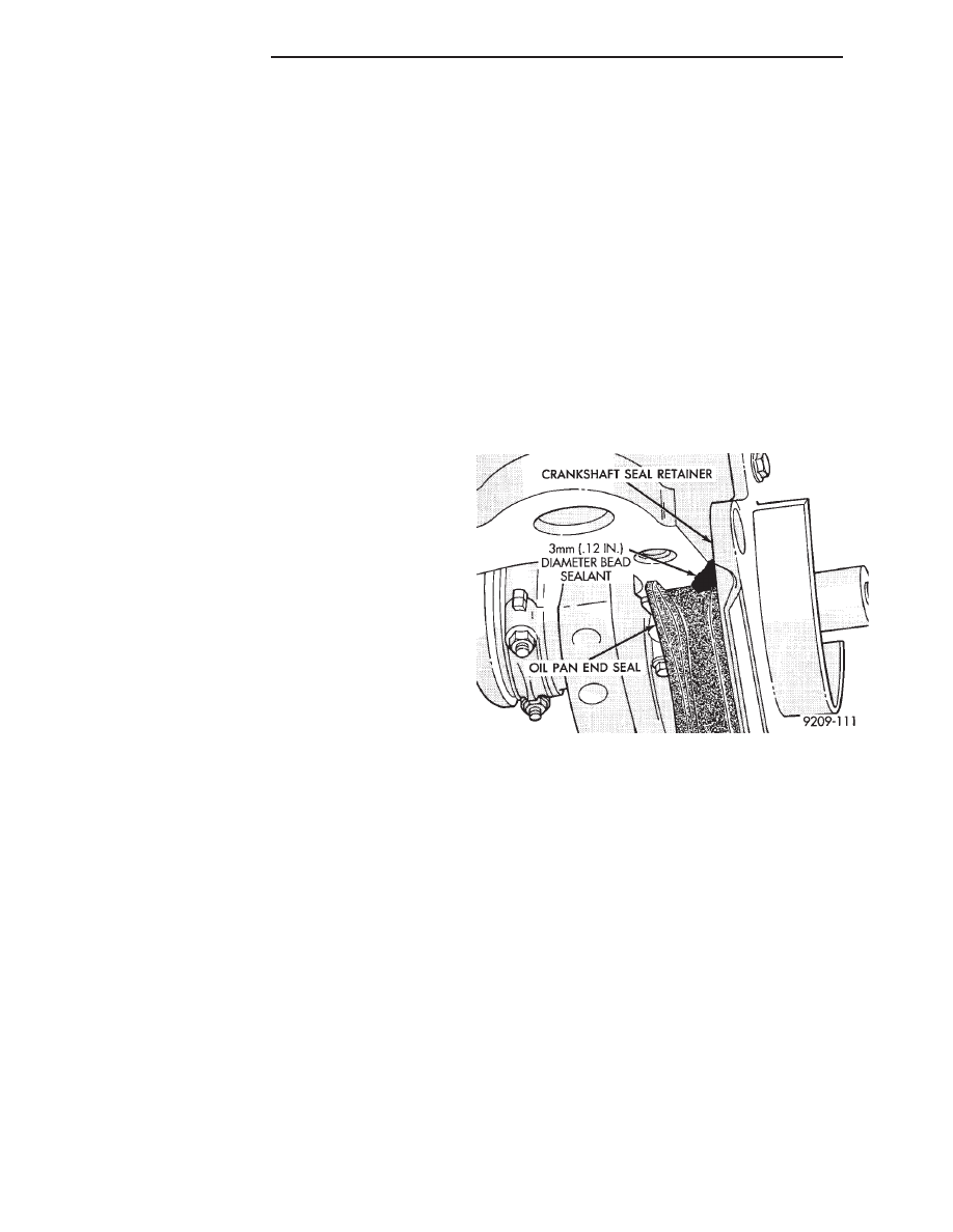
(1) Apply Mopar Silicone Rubber Adhesive Sealant
or equivalent at the front seal retainer parting line
(Fig. 3).
(2) Install the oil pan side gaskets to the block. Use
heavy grease or Mopar Silicone Rubber Adhesive Seal-
ant or equivalent to hold in place.
(3) Apply Mopar Silicone Rubber Adhesive Sealant
or equivalent to ends of new oil pan end seals at
junction of cylinder block pan rail gasket (Fig. 3).
(4) Install pan and tighten to (12) M8 screws to 23
N
Im (200 in. lbs.) and 1 M6 screws to 12 NIm (105 in.
lbs.).
OIL PUMP SERVICE
OIL PICKUP
(1) Remove screw on pump cover holding oil pick-up
tube to oil pump (Fig. 4).
(2) Remove oil pick-up tube. When reinstalling
make sure to use a new O-Ring on pickup tube.
Fig. 3 Sealing, Front and Rear End Seals
9 - 58
2.2/2.5L ENGINE
Ä