Chrysler Le Baron, Dodge Dynasty, Plymouth Acclaim. Manual - part 357


  Index      Dodge     Chrysler Le Baron, Dodge Dynasty, Plymouth Acclaim - service repair manual 1993 year


Search            


Content   ..  355  356  357  358   ..


Chrysler Le Baron, Dodge Dynasty, Plymouth Acclaim. Manual - part 357


rivet with a 1/4 inch diameter drill. Remove retain-
ing screws if necessary (Fig. 11 through 14).

(3) Maneuver the motor end of the flex drive reg-

ulator outside of the large inside panel access hole
and rotate regulator out of door.

(4) If the window motor cannot be actuated and is

stuck or frozen in any position other than at the ac-
cess hole, the removal procedure is as follows:

(a) Remove the regulator attaching rivets by

knocking out the rivet center mandrel and drilling
the rivets with a 1/4 inch diameter drill. Remove
retaining screws if necessary.

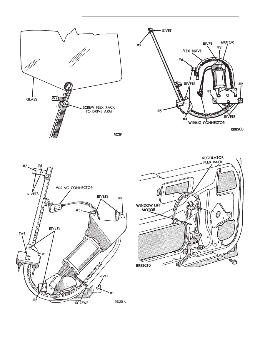
Fig. 10 Window Regulator Flex Rack to Drive Arm

Fig. 11 Flex Drive Window Regulator Rear Door—AP

Body

Fig. 12 Flex Drive Window Regulator Front

Door—AG Body

Fig. 13 Door Power Window—AG Body

8S - 6

POWER WINDOWS

Ä

(b) Manually lift the window upward with the

unriveted flex drive electric regulator still attached
until the screw can be removed. If more access is
needed, remove the two screws that hold the
T-track to the motor gearbox. This will allow re-
moval of the motor from the T-track.
(5) Remove two screws that fasten the motor gear-

box to the metal T-track.

(6) Perform bench test.

BENCH TEST

(1) Connect positive (+) lead from test battery to

either of the two motor terminals.

(2) Connect negative (-) lead from test battery to

remaining motor terminal.

(3) The motor will now rotate in one direction.
(4) Reverse the battery leads and the motor should

now rotate in the opposite direction.

(5) If the motor does not rotate in both directions,

replace the motor.

INSTALLATION

(1) Install new motor on T-track using No. 8-32 X

1/2 screws tighten to 4 N

Im (40 in. lbs.) torque.

(2) Feed top of T- track into access hole and point

and rotate it towards the hinge pillar until regulator
motor is approximately horizontal. Then rotate regu-
lator in the opposite direction about a 1/4 turn and
line up bracket tab to inner panel slot.

(3) Fasten regulator with the rivet sequence shown

in (Figs. 10 and 11).

(4) Actuate the motor until the flex rack is visible

within the access slot. Attach the window and drive

arm assembly to the flex rack with the screws.
Tighten screws to 4 N

Im (40 in. lbs.) torque.

POWER WINDOW CABLE HOUSING/MOTOR
REPLACEMENT—AC and AY Bodies

WARNING: REMOVAL OF THE WINDOW LIFT MO-
TOR FROM THE REGULATOR WILL CAUSE THE
ASSIST SPRING TO UNWIND RAPIDLY WITH THE
POTENTIAL OF CAUSING PHYSICAL INJURY. IF
THE WINDOW LIFT MOTOR REQUIRES REPLACE-
MENT, SEE REGULATOR REPLACE CABLE AND
DRUM IN THIS GROUP OF THIS MANUAL.

(1) Remove front door trim panel. Refer to group

23, Body.

(2) Disconnect window lift plate from glass (Fig.

15).

(3) Disconnect window track from door.
(4) Disconnect window lift motor and drive cables.
(5) Disconnect electrical connections.
(6) Carefully remove window track, cables and lift

motor assembly from door.

(7) For installation reverse above procedures.

MOTOR REPLACEMENT

(1) Refer to Front Door Window Regulator for re-

moval.

(2) The door glass must be in the down position.
(3) Tape glass to door frame to hold glass in the up

position.

(4) If the window is not in the full up position, re-

move only the motor from the door.

(5) Remove nuts from motor and cable housing

(Fig. 16).

(6) Make sure motor is facing you before separat-

ing motor from housing.

(7) Using a flat tool slowly separate motor from

housing, making sure the cable drum under the mo-
tor stays in cable housing. When motor is fully sep-
arated the assist spring will be completely unwound
(Fig. 17).

(8) Remove assist spring by releasing the tabs on

the opposite sides of the spring, do not remove spring
from its case (Fig. 18).

Fig. 14 Rear Door Power Window—AP Body

ART: 928s-3; SIZE (1) = 1-3/4h x 3-1/2w

Fig. 15 Cable and Housing/Motor

Ä

POWER WINDOWS

8S - 7

INSTALLATION

(1) Install motor into housing with one stud and in

center of housing to secure motor to housing.

(2) Before installing new spring, power the motor

into the full-up position.

(3) Replace assist spring on cable housing. Wind

spring counter clockwise 3 1/2 turns on the left door.
The right door, wind spring clockwise 3 1/2 turns
(Fig. 19).

(4) Install the other two studs and nuts and

tighten to 4 to 5 M

Im (35 to 45 in. lbs.) torque.

(5) Inspect that cables are not twisted prior to in-

stalling motor and housing into door.

QUARTER WINDOW REPLACEMENT—AJ BODY

For steps (1) through (5) refer to Group 23, Body,

for complete procedures.

(1) Remove the folding top sling well assembly.
(2) Remove the quarter trim upper moldings.
(3) Remove the cowl trim and scuff plate panels.
(4) Remove the rear seat cushion.
(5) Remove the quarter trim and rear seat back as-

sembly.

(6) Remove quarter windows assembly (Fig. 20).

Fig. 16 Separating Motor from Housing

Fig. 17 Cable/Drum and Motor

Fig. 18 Assist Spring Cover

Fig. 19 Wind Assist Spring Cover

Fig. 20 Power Quarter Window—AJ Body

8S - 8

POWER WINDOWS

Ä

(a) Position window approximately one-third the

way up.

(b) Remove glass stabilizer.
(c) Disconnect window motor wiring.
(d) Remove three quarter window assembly at-

taching screws and lift window assembly out of ve-
hicle.
(7) For installation reverse above procedure. Refer

to Group 23, Body, for window glass adjustment.

QUARTER WINDOW MOTOR REPLACEMENT—AJ
BODY

(1) Remove window assembly from car and have

window in mid position (halfway up).

(2) Remove No. 1 and No. 2 lower motor mounting

screws (Fig. 21) and loosen No. 3 to allow the motor
to pivot around the third screw. This will allow easy
removal of the glass and lift plate assembly and also
allow some tension to be relieved from the cables.

(3) Remove the mounting nuts on the lift plate and

remove the glass and lift plate assembly.

(4) Remove motor from regulator plate.

(5) Remove cover plate on cable drum housing

(Fig. 22).

CAUTION: Cable drum may pop up and out of hous-
ing due to residual tension remaining on cables.

(6) Pull drum out of the motor housing. Remove

cables from drum, paying very close attention to the
cable routing on the drum.

(7) Inspect the cables for signs of wear. If neces-

sary, replace the cables with Mopar Cable Replace-
ment Package.

(8) Rewind cables on new cable drum.
(9) Dab grease on internal motor shocks. Place in

drum and install drum into the new housing.

(10) Install housing cover plate.
(11) Mount motor on regulator plate by inserting a

guide pin through No. 3 motor mount screw hole and
pivot motor around this point. Install No. 1 mounting
screw and bushing. Replace remaining screws and
bushings and tighten to 2 N

Im (20 in. lbs.) torque.

(12) Lubricate with grease the areas of guide rail

where cable and glider assembly travel.

(13) Run assembly up and down to verify correct

cable routing.

(14) Loosen motor mounting screws to allow reas-

sembly of lift plate onto regulator. Tighten lift plate
nuts to 5 N

Im (50 in. lbs.) torque. Tighten motor

mounting screws to 2 N

Im (20 in. lbs.) torque.

Fig. 21 Quarter Window Lift Mechanism—AJ Body

Fig. 22 Cable Drum and Lift Cable—AJ Body

Ä

POWER WINDOWS

8S - 9


Content   ..  355  356  357  358   ..