Chrysler Le Baron, Dodge Dynasty, Plymouth Acclaim. Manual - part 311


  Index      Dodge     Chrysler Le Baron, Dodge Dynasty, Plymouth Acclaim - service repair manual 1993 year


Search            


Content   ..  309  310  311  312   ..


Chrysler Le Baron, Dodge Dynasty, Plymouth Acclaim. Manual - part 311


(7) Unscrew lighter receptacle shell from element

and remove.

(8) For installation reverse above procedures.

INSTRUMENT PANEL ROLL DOWN PROCEDURE

CAUTION: Disconnect negative battery cable, in en-
gine

compartment,

before

servicing

instrument

panel.

(1) Remove instrument panel center bezel (Fig.

31).

(2) Remove upper and lower steering column cov-

ers.

(3) Remove the left under panel silencer.
(4) Set parking brake.
(5) Remove console side carpet panels (Fig. 32).
(6) Remove console, refer to Group 23, Body.
(7) Remove transmission range clip and cable loop

end from post on gear shifter (Fig. 33 and 34).

(8) Remove adjuster from tab on gear shifter

bracket. By pushing in locking knob on adjuster, and
sliding the adjuster off the tab on the gear shifter
bracket.

(a) For installation: insert transmission range

cable into adjuster and line up with the end of the
adjuster.

(b) The transmission range indicator must be ad-

justed with the gear shifter in low position.

(c) Check the gear selector indicator for proper

alignment.

(d) Attach transmission range clip to the ad-

juster to secure cable.
(9) Remove two screws and slide Air Bag Diagnos-

tic Module out of right side of instrument panel cen-
ter stack area, then disconnect wiring.

(10) Remove screw from instrument panel dimmer

module at left of steering column and lower module.

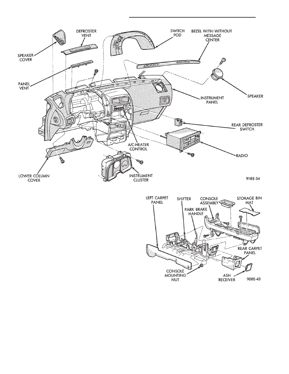
Fig. 31 Instrument Panel Components

Fig. 32 Center Console

8E - 56

INSTRUMENT PANEL AND GAUGES

Ä

(11) Remove two screws from fuse block and lower

fuse block.

(12) Remove three screws from hood release and

lower hood release handle.

(13) Remove flasher relay from bracket on center

distribution duct.

(14) Remove screw from ATC sensor motor assem-

bly and unhook from bracket if equipped.

(15) Remove the radio ground screw above flasher

relay mount.

(16) Remove center distribution duct screw from

left instrument panel lower brace, then remove four
screws to remove left lower brace.

(17) Remove five nuts on steering column and drop

column, then remove two upper column attaching studs.

(18) Remove two screws and pull out compact disc

player or cubby box, disconnect Co-Axial cable from
compact disc player.

(19) Remove Electronic Vehicle Information Center

(E.V.I.C.) or Traveler from vehicle.

(20) Remove radio.
(21) Remove A.T.C., A/C or heater controls.

(22) Squeeze latches on side of Rear Window defog-

ger switch and remove.

(23) Snap off cluster lower trim bezel, switch pod

vent grille, speaker grilles and defroster grilles.

(24) Remove switch pod assembly.
(25) Remove cluster assembly.
(26) Remove dash speakers.
(27) Snap out bezel with or without message center

and disconnect wiring.

(28) Open glovebox door, squeeze sides and roll

glovebox completely open. Remove glovebox light
switch, and disconnect wires.

(29) Loosen right cowl side pivot bolt through

glovebox opening then close glovebox.

(30) Loosen left cowl side pivot.
(31) Remove four screw attachments at top of in-

strument panel and roll panel out.

(32) Pull wiring, antenna cable, A/C cable and vac-

uum lines out of instrument panel. Disconnect demis-
ter hose and remove instrument panel with ducts
attached.

(33) Transfer ducts and brackets onto new panel.
(34) For instrument panel roll up, reverse

above procedures.

INTERIOR LAMP REMOVAL

The Dome, Floor Console and Door Lamps operate

when the doors are open or headlamp switch is
placed in courtesy position.

DOME LAMP

(1) Pry either the forward or rearward edge of the

dome lamp to free it from retaining bracket.

(2) Pry either the forward or rearward edge of the

lens away from the bezel and replace lamp.

(3) For installation reverse above procedures.

FRONT HEADER READING LAMP

Pull lamp from headliner. Disconnect wiring and

replace lamp.

FLOOR CONSOLE LAMP

Pry along top edge of lamp and pivot lamp out of

floor console, the lens does not remove. Remove lamp
and twist out lamp socket. Replace lamp.

DOOR LAMPS

Pry along bottom edge of lamp and pivot lamp out

of door trim panel, the lens does not remove. Remove
lamp and twist out lamp socket. Replace lamp.

DOOR REFLECTORS

Pry reflector away from the door trim panel, and

replace.

TRUNK LAMP

Remove lens by prying lens out of trunk trim panel

and replace bulb.

Fig. 33 Transmission Range Cable

Fig. 34 Cable Adjustment

Ä

INSTRUMENT PANEL AND GAUGES

8E - 57

AP BODY

INDEX

page

page

Cluster and Gauge Service and Testing

. . . . . . . 58

Gauges

. . . . . . . . . . . . . . . . . . . . . . . . . . . . . . . . 61

General Information

. . . . . . . . . . . . . . . . . . . . . . . 58

Instrument Panel Replacement

. . . . . . . . . . . . . . 72

Interior Lamp Replacement

. . . . . . . . . . . . . . . . . 73

Switch and Panel Component Service

. . . . . . . . . 67

GENERAL INFORMATION

INSTRUMENT CLUSTER

There are two conventional instrument cluster as-

semblies available. The clusters incorporates mag-
netic type gauges and an electronically driven
speedometer and odometer assembly (Fig. 1 and 2).

MAGNETIC GAUGES

All gauges on the AP Body clusters are the mag-

netic type gauges. When the ignition switch is in the
OFF position each gauge, except for the voltmeter
and tachometer will show a reading. However, the
readings are only accurate when the ignition switch
is in the ON position.

TACHOMETER DRIVE MODULE

The tachometer drive module is an electronic mod-

ule used to drive the magnetic tachometer in the
high line cluster.

This module is located on top of the instrument

cluster.

ELECTRONIC DIGITAL CLOCK

The electronic digital clock is in the radio. The

clock and radio each use the display panel built into
the radio. A digital readout indicates the time in
hours and minutes whenever the ignition switch is in
the ON or ACC position.

When the ignition switch is in the OFF position, or

when the radio frequency is being displayed, time
keeping is accurately maintained.

The procedure for setting the clock varies slightly

with each radio. The correct procedure is described
under the individual radio operating instructions re-
fer to the Sound Systems Manual supplied with the
vehicle.

WARNING LAMPS AND INDICATOR LIGHTS

The instrument cluster has warning and indicators

lamps for eight different systems:
• Low oil pressure

• Brake warning

• Seat belt warning

• Malfunction indicator (check engine) lamp

• Air Bag

• High beam indicator

• Right and left turn signals.

• Anti-lock (ABS)

CLUSTER AND GAUGE SERVICE AND TESTING

CAUTION: Disconnect the negative battery cable
before servicing the instrument panel. When power
is required for test purposes, reconnect battery ca-
ble for test only. Disconnect the negative battery
cable after test and before continuing service pro-
cedures.

SENDING UNIT TEST

Check for a defective sending unit or wiring, when

a problem occurs with a cluster gauge. Do this before
disassembling the cluster.

(1) Sending units and wiring can be checked by

grounding the connector leads, at the sending unit,
in the vehicle.

(2) With the ignition in the ON position, a

grounded input will cause the fuel or temperature
gauge to read at or above maximum.

Fig. 1 Instrument Cluster With Tachometer

Fig. 2 Instrument Cluster Without Tachometer

8E - 58

INSTRUMENT PANEL AND GAUGES

Ä

FUEL TANK SENDING UNIT TEST

Refer to Group 14, Fuel for test procedures.

LOW OIL PRESSURE WARNING LAMP TEST

The low oil pressure warning lamp will illuminate

when the ignition key is turned to the ON position
without engine running. The lamp also illuminates
should the engine oil pressure drop below a safe oil
pressure level.

To test the system turn ignition key to the ON po-

sition. If the lamp fails to light, inspect for a broken
or disconnected wire at the oil pressure combination
unit, located at the front of the engine (Fig. 3). If the
wire at the connector checks good, pull connector
loose from the switch and with a jumper wire ground
connector to the engine. With the ignition key turned
to the ON position check the warning lamp. If lamp
still fails to light, inspect for a burned out lamp or
disconnected socket in the cluster.

COMBINATION OIL SENDING UNIT TEST

The combination oil sending unit has two func-

tions:

(1) The normal closed circuit keeps the oil pressure

warning lamp on until there is oil pressure (Fig. 4).

(2) The sending unit provides a resistance that

varies with oil pressure.

To test the normally closed oil lamp circuit, discon-

nect the locking connector and measure the resis-
tance between the switch terminal and the metal
housing. The ohmmeter should read continuity. Start
the engine.

If there is oil pressure, the ohmmeter should read

an open circuit.

To test the sending unit, measure the resistance

between the sending unit terminal and the metal
housing. The ohmmeter should no continuity. Start
the engine.

The ohmmeter should read between 30 to 55 ohms,

depending on engine speed, oil temperature and oil
viscosity.

If the above results are not obtained, replace the

sending unit.

SEAT BELT WARNING SYSTEM

For testing of this system refer to Group 8M, Re-

straint Systems.

AIR BAG WARNING SYSTEM

For testing of this system refer to Group 8M, Re-

straint Systems.

MALFUNCTION INDICATOR (CHECK ENGINE)
SYSTEM

For testing of this system using DRB II, refer to

the Body Powertrain Diagnostic Procedures.

BRAKE SYSTEM WARNING LAMP TEST

The brake warning lamp illuminates when parking

brake is applied with ignition key turned ON. The
same lamp will also illuminate should one of the two
service brake systems fail when brake pedal is ap-
plied. Refer to Brake system warning Lamp Diagno-
sis (Fig. 5).

To test system turn ignition key ON and apply

parking brake. If lamp fails to light, inspect for a
burned out lamp, disconnected socket, a broken or
disconnected wire at switch. The lamp also lights
when the ignition switch is turned to start.

To test service brake warning system, raise vehicle

on a hoist and open a wheel cylinder bleeder while a
helper depresses brake pedal and observes warning
lamp. If lamp fails to light, inspect for a burned out
lamp, disconnected socket, a broken or disconnected
wire at switch.

If lamp is not burned out and wire continuity is

proven, replace brake warning switch in brake line
Tee fitting mounted on frame rail in engine compart-
ment below master cylinder (Fig. 6).

CAUTION: If wheel cylinder bleeder was opened
check master cylinder fluid level.

Fig. 3 Combination Oil Sending Unit

Fig. 4 Combination Oil Sending Unit Test

Ä

INSTRUMENT PANEL AND GAUGES

8E - 59


Content   ..  309  310  311  312   ..