Chrysler Le Baron, Dodge Dynasty, Plymouth Acclaim. Manual - part 294


  Index      Dodge     Chrysler Le Baron, Dodge Dynasty, Plymouth Acclaim - service repair manual 1993 year


Search            


Content   ..  292  293  294  295   ..


Chrysler Le Baron, Dodge Dynasty, Plymouth Acclaim. Manual - part 294


Refer to the appropriate Powertrain Diagnostics Pro-
cedure Manual. Refer to the wiring diagrams section
for circuit information.

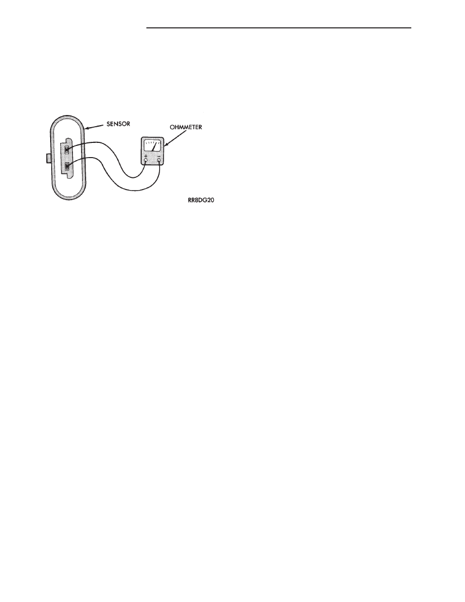
COOLANT TEMPERATURE SENSOR TEST

(1) With key off, disconnect wire connector from

coolant temperature sensor (Fig. 9).

(2) Connect one lead of ohmmeter to one terminal of

coolant temperature sensor.

(3) Connect the other lead of ohmmeter to remaining

terminal of coolant temperature sensor. The ohmmeter
should read as follows;
• Engine/Sensor hot at normal operating temperature
around 200°F should read approximately 700 to 1,000
ohms.
• Engine/Sensor at room temperature around 70°F,
ohmmeter should read approximately 7,000 to 13,000
ohms.

To test the coolant temperature sensor circuits,

refer to the DRBII scan tool and the appropriate
Powertrain Diagnostic Service manual.

MANIFOLD ABSOLUTE PRESSURE (MAP) SENSOR
TEST

Refer to the appropriate Powertrain Diagnostic Pro-

cedure manual.

CRANKSHAFT POSITION SENSOR AND CAMSHAFT
POSITION SENSOR TESTS

Refer to the appropriate Powertrain Diagnostic Pro-

cedure manual.

Fig. 9 Coolant Temperature Sensor Test

8D - 38

IGNITION SYSTEMS

Ä

2.2L TURBO III, 3.3L AND 3.8L IGNITION SYSTEMS—SERVICE PROCEDURES

INDEX

page

page

Camshaft Position Sensor Service—Turbo III Engine . 42
Camshaft Position Sensor—3.3L and 3.8L Engines

. 43

Coolant Temperature Sensor—3.3L and 3.8L

Engines

. . . . . . . . . . . . . . . . . . . . . . . . . . . . . . 39

Coolant Temperature Sensor—Turbo III

. . . . . . . . 39

Crankshaft Position Sensor—3.3L and 3.8L Engines . 42
Crankshaft Position Sensor—Turbo III Engine

. . . 42

Idle RPM Test

. . . . . . . . . . . . . . . . . . . . . . . . . . . 41

Ignition Coil Service—Turbo III Engine

. . . . . . . . 43

Ignition Coil—3.3L and 3.8L Engine

. . . . . . . . . . . 43

Knock Sensor—Turbo III Engines

. . . . . . . . . . . . 40

Manifold Absolute Pressure (MAP) Sensor—3.3L

and 3.8L Engines

. . . . . . . . . . . . . . . . . . . . . . . 44

Manifold Absolute Pressure (MAP) Sensor—

Turbo III Engine

. . . . . . . . . . . . . . . . . . . . . . . . 44

Powertrain Control Module (PCM)

. . . . . . . . . . . . 39

Spark Plug Cable Service

. . . . . . . . . . . . . . . . . . 40

Spark Plug Service

. . . . . . . . . . . . . . . . . . . . . . . 41

POWERTRAIN CONTROL MODULE (PCM)

REMOVAL

(1) Remove air cleaner duct or air cleaner assem-

bly.

(2) Remove battery.
(3) Remove

powertrain

control

module

(PCM)

mounting screws (Fig. 1).

(4) Remove 60-way connector from PCM. Remove

PCM.

INSTALLATION

(1) Connect 60-Way connector to PCM (Fig. 1).
(2) Install PCM on inside left front fender. Install

and tighten mounting screws.

(3) Install the battery.
(4) Install air cleaner duct or air cleaner assembly.

COOLANT TEMPERATURE SENSOR—TURBO III

The coolant sensor threads into the thermostat

housing (Fig. 2).

REMOVAL

(1) Drain cooling system until coolant level is be-

low thermostat housing. Refer to Group 7, Cooling
System.

(2) Remove air cleaner fresh air duct.
(3) Disconnect electrical connector from coolant

sensor.

(4) Remove sensor from thermostat housing (Fig.

2).

INSTALLATION

(1) Install sensor. Tighten to 7 N

Im (60 in. lbs.)

torque.

(2) Connect electrical connector to coolant sensor
(3) Fill cooling system. Refer to Group 7, Cooling

System.

(4) Install fresh air duct.

COOLANT TEMPERATURE SENSOR—3.3L AND
3.8L ENGINES

The coolant temperature sensor is located below

the ignition coil (Fig. 3).

REMOVAL

(1) Drain cooling system until coolant level is be-

low coolant sensor. Refer to Group 7, Cooling System.

(2) Remove electrical connector from coil (Fig. 4).
(3) Remove coil mounting screws.
(4) Rotate coil away from coolant temperature sen-

sor.

Fig. 1 Powertrain Control Module (PCM)

Fig. 2 Coolant Temperature Sensor—Turbo III

Ä

IGNITION SYSTEMS

8D - 39

(5) Disconnect electrical connector from coolant

temperature sensor.

(6) Remove sensor from engine.

INSTALLATION

(1) Tighten the coolant sensor to 7 N

Im (60 in. lbs.)

torque.

(2) Connect electrical connector to sensor.
(3) Fill cooling system. Refer to Group 7, Cooling

System.

(4) Install coil. Tighten coil mounting screws to 12

N

Im (105 in. lbs.) torque.

(5) Connect electrical connector to coil.

KNOCK SENSOR—TURBO III ENGINES

The knock sensor is located on the intake manifold,

behind the PCV breather (Fig. 5).

REMOVAL

(1) Remove PCV breather.
(2) Remove harness connector from the knock sen-

sor.

(3) Remove knock sensor.

INSTALLATION

(1) Install knock sensor. Tighten sensor to 9 N

Im

(7 ft. lbs) torque.

(2) Connect harness connector to sensor.
(3) Install PCV breather.

SPARK PLUG CABLE SERVICE

Clean high tension cables with a cloth moistened

with a non-flammable solvent. Wipe the cables dry.
Check for brittle or cracked insulation.

When testing cables for punctures and cracks with

an oscilloscope, follow the instructions of the equip-
ment manufacturers.

CAUTION: Do not leave any one spark plug cable
disconnected any longer than necessary during test
or possible heat damage to catalytic converter will
occur. Total test time must not exceed ten minutes.

If an oscilloscope is not available, cables can be

tested as follows:

(1) With the engine not running, connect one end

of a test probe to a good ground. Use a probe made of
insulated wire and insulated alligator clips on each
end.

WARNING: THE ENGINE DIRECT IGNITION SYSTEM
GENERATES

APPROXIMATELY

40,000

VOLTS.

PERSONAL INJURY COULD RESULT FROM CON-
TACT WITH THIS SYSTEM.

Fig. 3 Coolant Temperature Sensor—3.3L and 3.3L

Engine

Fig. 4 Ignition Coil Removal

Fig. 5 Knock Sensor—Turbo III Engine

8D - 40

IGNITION SYSTEMS

Ä

(2) With engine running, move test probe along

entire length of all cables (approximately 0 to 1/8
inch gap). If punctures or cracks are present there
will be a noticeable spark jump from the faulty area
to the probe. Cracked, leaking or faulty cables should
be replaced.

Use the following procedure when removing the

high tension cable from the spark plug. First, remove
the cable from the retaining bracket. Then grasp the
terminal as close as possible to the spark plug. Ro-
tate the cover (boot) slightly and pull straight back.
Do not use pliers and do not pull the cable at an
angle. 
Doing so will damage the insulation, cable
terminal or the spark plug insulator. Wipe spark
plug insulator clean before reinstalling cable
and cover.

Resistance cables are identified by the words Elec-

tronic Suppression.

Use an ohmmeter to check cables for opens, loose

terminals or high resistance.

(a) Remove cable from spark plug.
(b) Remove cable from the coil tower.
(c) Connect the ohmmeter between spark plug

end terminal and the coil end terminal. Resistance
should be within tolerance shown in the cable re-
sistance chart. If resistance is not within tolerance,
replace cable assembly. Test all spark plug cables
in same manner.

SPARK PLUG SERVICE

When replacing the spark plug cables, route the ca-

bles correctly and secure them in the appropriate re-
tainers. Incorrectly routed cables can cause the radio
to reproduce ignition noise. It can also cause cross ig-
nition of the spark plugs or short circuit the cables to
ground.

SPARK PLUG REMOVAL

Always remove cables by grasping at boot, rotating

the boot 1/2 turn, and pulling straight back in a
steady motion.

(1) Prior to removing the spark plug spray com-

pressed air around the spark plug hole and the area
around the spark plug.

(2) Remove the spark plug using a quality socket

with a rubber or foam insert.

(3) Inspect the spark plug condition. Refer to

Spark Plug Condition in this section.

SPARK PLUG GAP ADJUSTMENT

Check the spark plug gap with a gap gauge. If the

gap is not correct, adjust it by bending the ground
electrode (Fig. 6).

SPARK PLUG INSTALLATION

(1) To avoid cross threading, start the spark plug

into the cylinder head by hand.

(2) Tighten spark plugs to 28 N

Im (20 ft. lbs.)

torque.

(3) Install spark plug cables over spark plugs.

IDLE RPM TEST

WARNING: BE SURE TO APPLY PARKING BRAKE
AND/OR BLOCK WHEELS BEFORE PERFORMING
ANY ENGINE RUNNING TESTS.

Engine idle set rpm should be tested and recorded

as it is when the vehicle is first brought into shop
for testing. 
This will assist in diagnosing complaints
of engine stalling, creeping and hard shifting on ve-
hicles equipped with automatic transaxle. Refer to the
Throttle Body Minimum Airflow procedures in Group
14.

IGNITION TIMING PROCEDURE

Ignition timing cannot be changed or set on Turbo

III, 3.3L or 3.8L engines. For diagnostic information,
refer to the DRBII scan tool and the appropriate
Powertrain Diagnostics Procedures manual.

CABLE RESISTANCE CHART

Fig. 6 Setting Spark Plug Gap—Typical

Ä

IGNITION SYSTEMS

8D - 41


Content   ..  292  293  294  295   ..