Chrysler Le Baron, Dodge Dynasty, Plymouth Acclaim. Manual - part 217


  Index      Dodge     Chrysler Le Baron, Dodge Dynasty, Plymouth Acclaim - service repair manual 1993 year


Search            


Content   ..  215  216  217  218   ..


Chrysler Le Baron, Dodge Dynasty, Plymouth Acclaim. Manual - part 217


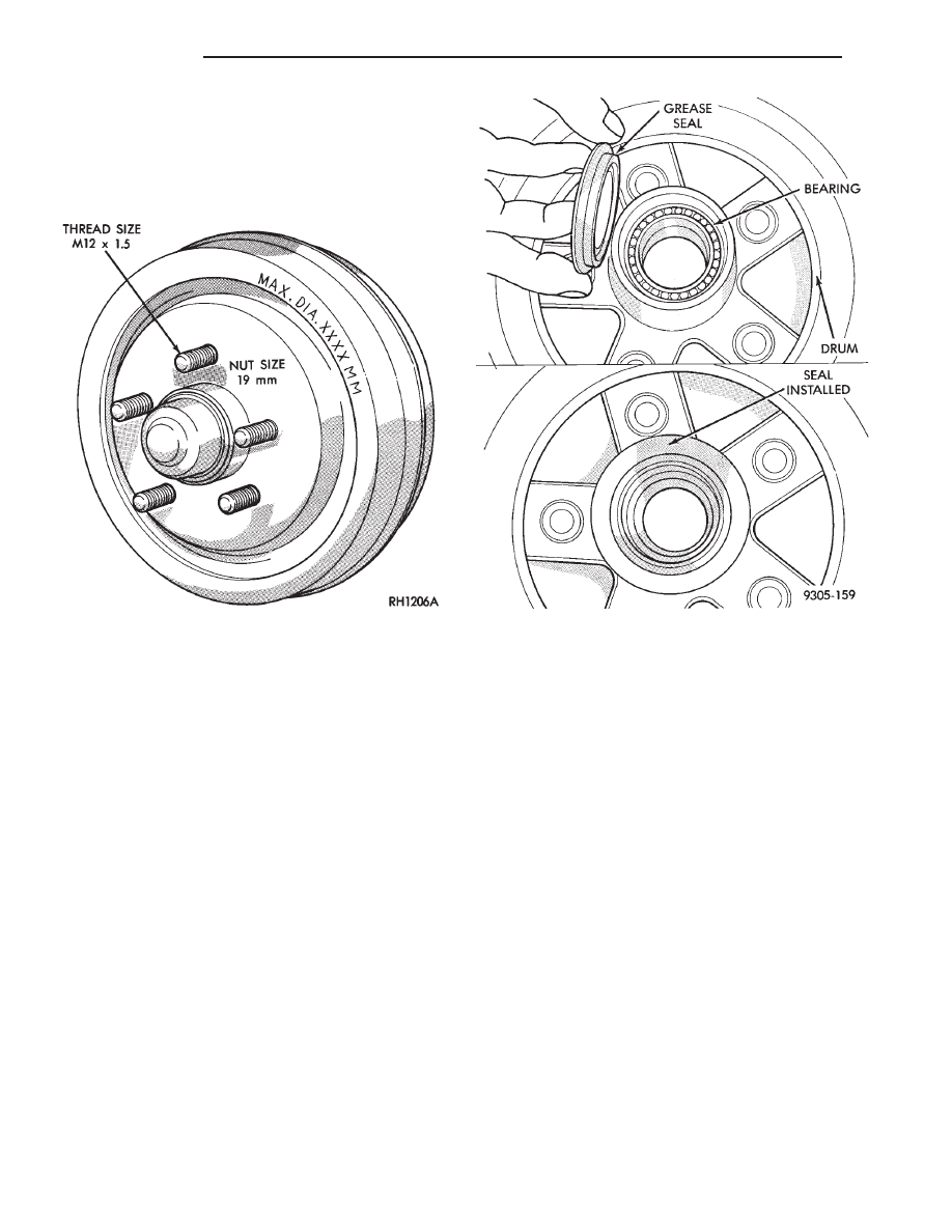
Using suitable tool, remove grease seal from drum

hub. Clean, inspect and pack wheel bearings. Install
new seal (Fig. 13). See Wheel Bearings section in
this group of the service manual for detailed infor-
mation on the wheel bearings, and service proce-
dures.

Fig. 12 Maximum Drum Diameter Identification

Fig. 13 Installing Grease Seal

5 - 22

BRAKES

Ä

WHEEL CYLINDERS

INDEX

page

page

General Information

. . . . . . . . . . . . . . . . . . . . . . . 23

Installing Wheel Cylinders

. . . . . . . . . . . . . . . . . . 24

Service Procedures

. . . . . . . . . . . . . . . . . . . . . . . 23

GENERAL INFORMATION

The piston boots are of the push-on type and pre-

vent moisture from entering the wheel cylinder.

To perform service operations or inspections of the

rear wheel brake cylinders. It will be necessary to re-
move the cylinders from the support plate and disas-
semble on the bench.

CAUTION: Wheel cylinders with cup expanders
must have cup expanders after any service proce-
dures (reconditioning or replacement).

SERVICE PROCEDURES

REMOVING WHEEL CYLINDERS FROM BRAKE
SUPPORT PLATES

With brake drums removed, inspect the wheel cyl-

inder boots for evidence of a brake fluid leak. Then
block the brake pedal in the stroke position, and vi-
sually check the boots for cuts, tears, or heat cracks.
If any of these conditions exist, the wheel cylinders
should be completely cleaned, inspected and new
parts installed. (A slight amount of fluid on the boot
may not be a leak, but may be preservative fluid
used at assembly.)

(1) In case of a leak, remove brake shoes, (replace

if soaked with grease or brake fluid.)

(2) Thoroughly clean area of wheel cylinder, where

hydraulic brake line connects to wheel cylinder. Dis-
connect hydraulic brake tube from wheel cylinder
(Fig. 1).

(3) Remove the rear wheel cylinder attaching bolts

(Fig. 1). Then pull wheel cylinder assembly off the
brake support plate (Fig. 2).

(4) Clean the surface sealant off the support plate

and wheel cylinder surfaces.

DISASSEMBLING WHEEL CYLINDERS

To disassemble the wheel cylinders, (Fig. 3) pro-

ceed as follows:

(1) Pry boots away from cylinders and remove.
(2) Press IN on one piston to force out opposite pis-

ton, cup and spring (with cup expanders). Then using
a soft tool such as a dowel rod, press out the cup and
piston that remain in the wheel cylinder.

(3) Wash wheel cylinder, pistons, and spring in

clean brake fluid or alcohol; (DO NOT USE ANY
PETROLEUM BASE SOLVENTS) 
clean thor-

oughly and blow dry with compressed air. Inspect

Fig. 1 Brake Tube Disconnected

Fig. 2 Remove or Install Wheel Cylinder

Ä

BRAKES

5 - 23

cylinder bore and piston for scoring and pitting. (Do
not use a rag as lint from the rag will stick to bore
surfaces.)

Wheel cylinder bores and pistons that are scored or

pitted in any way should be replaced. Cylinder walls
that have light scratches, or show signs of corrosion,
can usually be cleaned with crocus cloth, using a cir-
cular motion. Black stains on the cylinder walls are
caused by piston cups and will not impair operation
of cylinder.

ASSEMBLING WHEEL CYLINDERS

Before assembling the pistons and new cups in the

wheel cylinders, dip them in clean brake fluid. If the
boots are deteriorated, cracked or do not fit tightly
on the pistons or the cylinder casting, install new
boots.

(1) Coat cylinder bore with clean brake fluid.
(2) Install expansion spring with cup expanders in

cylinder. Install cups in each end of cylinder with
open end of cups facing each other (Fig. 3).

(3) Install piston in each end of cylinder having

the flat face of each piston contacting the flat face of
each cup, already installed (Fig. 3).

(4) Install a boot over each end of cylinder. Be

careful not to damage boot during installation.

INSTALLING WHEEL CYLINDERS

(1) Apply Mopar

t Gasket In-A-Tube or equivalent

sealant around wheel cylinder mounting surface (Fig.
4).

(2) Install wheel cylinder onto brake support, and

tighten the wheel cylinder to brake support plate at-
taching bolts to 8 N

Im (75 in. lbs.).

(3) Attach hydraulic brake tube to wheel cylinder,

and tighten tube to wheel cylinder fitting to 17 N

Im

(145 in. lbs.).

(4) Install brake shoes on support plate.
(5) Install rear brake drum onto rear hub. Install

rear wheel and tire assembly, tighten wheel stud
nuts to 115 N

Im (85 ft. lbs.).

(6) Adjust the rear brakes, (See Adjusting Service

Brakes) in Service Adjustments section in this group
of the service manual.

(7) Bleed the entire brake system. See (Bleeding

Brake System) in Service Adjustments section in this
group of the service manual.

Fig. 3 Rear Wheel Cylinder

Fig. 4 Apply Sealant on Support Plate

5 - 24

BRAKES

Ä

BRAKE SUPPORT ASSEMBLY

REMOVAL

Back off parking brake adjusting nut to provide

slack in cable.

With wheel and brake drum removed, disconnect

hydraulic tube from wheel cylinder.Disconnect park-
ing brake cable and adjuster lever spring (Fig. 1).

Using a suitable tool such as an aircraft type hose

clamp, install the clamp over the retainer on the end
of the parking brake cable (Fig. 2). Compress cable
housing retainer and start housing out of support
plate (Fig. 2). Remove clamp when retainer is free
from the park brake cable mounting hole in the rear
brake support plate. Alternate method is to slide a
14 mm box wrench over housing end fitting com-
pressing the three fingers.

Remove attaching bolts and washers and separate

brake support and spindle from rear support trailing
arm.

INSTALLATION

Insert parking brake cable and housing into sup-

port plate.

Install support plate, spindle and gasket between

support plate and spindle on to rear suspension mem-
ber. Tighten support plate attaching bolts to 71 N

Im

(53 ft. lbs) torque.

Attach cable to parking brake lever.
Connect brake tube to wheel cylinder. Tighten

brake tube to wheel cylinder fitting to 17 N

Im (145

in. lbs.).

Install brake drum and wheel. Adjust and bleed

service brakes. Adjust parking brake.

Fig. 1 Removing Adjuster Lever Spring

Fig. 2 Removing Park Brake Cable From Support

Plate

Ä

BRAKES

5 - 25


Content   ..  215  216  217  218   ..