Chrysler Le Baron, Dodge Dynasty, Plymouth Acclaim. Manual - part 153


  Index      Dodge     Chrysler Le Baron, Dodge Dynasty, Plymouth Acclaim - service repair manual 1993 year


Search            


Content   ..  151  152  153  154   ..


Chrysler Le Baron, Dodge Dynasty, Plymouth Acclaim. Manual - part 153


REAR POWER DOOR LOCK ACTUATOR

REMOVAL (FIG. 30)

(1) Remove door trim panel, silencer pad, and wa-

ter shield.

(2) Raise door glass to full up position.
(3) Remove door speaker, if equipped.
(4) Disconnect actuator rod from door latch assem-

bly.

(5) Remove screws holding power lock actuator to

inner door panel and separate from door.

INSTALLATION

Reverse the preceding operation.

REAR DOOR GLASS

REMOVAL (FIG. 31)

(1) Remove door trim panel, silencer pad, and wa-

ter shield.

(2) Position door glass half way up in door glass

opening.

(3) Pull upward firmly at the front upper corner of

glass to disengage lower glass guide from run chan-
nel.

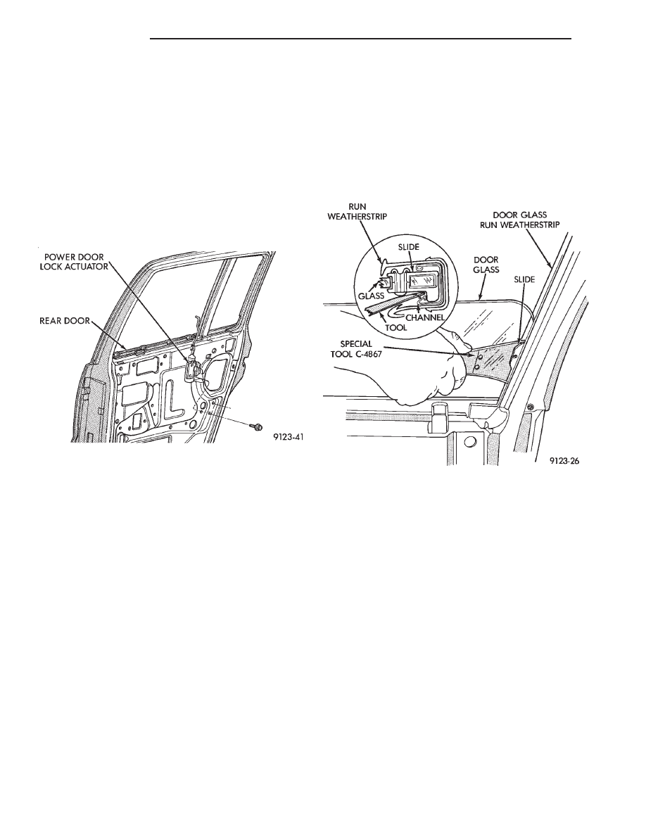
(4) Insert door glass removal tool C-4867 between

the glass slide and division run channel retaining lip
at approximately 50 mm (2 in.) down from top rear-
ward corner of glass. Push handle of tool toward
glass to open channel. Pull forward on the glass to
separate the slide from the channel.

(5) Position glass inboard of the division channel.

Pivot top of glass rearward between division channel
and inner door panel.

(6) Separate regulator lift arm roller from glass lift

channel. Hold regulator lift arm outward and lift
glass upward.

(7) Remove door glass through opening at top of

door.

INSTALLATION

(1) Lower door glass into opening at top of door.
(2) Insert window regulator lift arm roller into

glass lift channel.

(3) Push top of glass rearward to snap top slide

into division run channel.

(4) Push downward at front of glass to snap bottom

slide into channel.

(5) Install water shield, silencer pad and trim

panel.

REAR DOOR BELT MOULDING AND
WEATHERSTRIP

BELT MOULDING AND WEATHERSTRIP
REMOVAL (FIG. 32)

(1) Remove trim panel, silencer pad, and water

shield.

(2) Remove door glass.
(3) Remove screws holding belt moulding and

weatherstrip to outer door panel and separate moul-
ding from door.

BELT MOULDING AND WEATHERSTRIP
INSTALLATION

Reverse the preceding operation.

REAR DOOR GLASS RUN WEATHERSTRIP

REMOVAL (FIG. 33)

(1) Remove door belt moulding and weatherstrip

assembly.

(2) Pull door glass run weatherstrip from forward

lower channel and upper door frame back to division
channel.

Fig. 30 Rear Power Lock Actuator

Fig. 31 Rear Door Glass

23 - 22

AA-BODY

Ä

(3) Separate glass run weatherstrip from door.

INSTALLATION

(1) Insert glass run weatherstrip into top of glass

opening upper channel. Align molded corner of
weatherstrip to upper front corner of glass opening.

(2) Push weatherstrip into upper rear corner of

door frame above division channel.

(3) Install door belt moulding and weatherstrip as-

sembly.

REAR DOOR GLASS STATIONARY GLASS MODULE

STATIONARY GLASS MODULE REMOVAL
(FIG. 34)

(1) Remove belt moulding and weatherstrip assem-

bly.

(2) Remove upper window opening moulding.
(3) Remove bolts and screws holding division chan-

nel and glass module to door assembly and separate
module from door frame.

(4) Remove module through opening at top of door.

STATIONARY GLASS MODULE INSTALLATION

Reverse the preceding operation. Use two sided ad-

hesive tape to secure module weatherstrip to inside
of door frame.

REAR DOOR WINDOW REGULATOR/MANUAL

MANUAL WINDOW REGULATOR REMOVAL
(FIG. 35)

(1) Remove trim panel, silencer pad, and water

shield.

(2) Position door glass 150 mm (6 in.) up into glass

opening. Pull upward firmly at front edge of glass to
disengage lower glass run guide from division chan-
nel.

(3) Remove bolts holding window regulator to in-

ner door panel.

(4) Slide roller from window lift channel.
(5) By hand, pull glass upward to 25 mm (1 in.)

from full up position. Using suitable tape, secure
door glass to upper window frame.

(6) Remove regulator assembly from door.

MANUAL WINDOW REGULATOR
INSTALLATION

Reverse the preceding operation.

REAR DOOR WINDOW REGULATOR/POWER

POWER WINDOW REGULATOR REMOVAL
(FIG. 36)

(1) Remove trim panel, silencer pad, and water

shield.

Fig. 32 Rear Door Belt Moulding and Weatherstrip

Fig. 33 Rear Door Glass Run Weatherstrip

Fig. 34 Rear Door Stationary Glass Module

Ä

AA-BODY

23 - 23

(2) Position door glass 150 mm (6 in.) up into glass

opening. Firmly pull upward at front edge of glass to
disengage lower glass run guide from division chan-
nel.

(3) Remove bolts holding window regulator to in-

ner door panel.

(4) Slide roller from window lift channel.
(5) By hand, pull glass upward to 25 mm (1 in.)

from full up position. Using suitable tape, secure
door glass to upper window frame.

(6) Remove regulator assembly from door.

POWER WINDOW REGULATOR INSTALLATION

Reverse the preceding operation.

DOOR OPENING WEATHERSTRIPS

FRONT OR REAR DOOR OPENING
WEATHERSTRIP REMOVAL (FIG. 37)

(1) Remove interior trim as necessary to gain ac-

cess to door opening weatherstrip.

(2) Pull weatherstrip from pinch flange around

door opening.

FRONT OR REAR DOOR OPENING
WEATHERSTRIP INSTALLATION

(1) Locate the middle to the weatherstrip at the

center of the upper pinch flange. Push weatherstrip
onto pinch flange at the top corner near the B-pillar.

(2) When the weatherstrip has been installed down

the door opening to the sill pinch flange, mate the
ends of the weatherstrip together and finish install-
ing.

BODY SIDE MOULDING AND APPLIQUE

STICK-ON BODY SIDE MOULDING REMOVAL
AND INSTALLATION (FIG. 38)

(1) Warm the effected stick-on moulding and body

metal to approximately 38°C (100°F) using a suitable
heat lamp or heat gun.

(2) Pull stick-on moulding from painted surface.
(3) Remove adhesive tape residue from painted

surface of vehicle.

(4) If moulding is to be reused, Remove tape resi-

due from moulding. Clean back of moulding with Mo-
par,

Super

Kleen

solvent

or

equivalent.

Wipe

moulding dry with lint free cloth. Apply new body
side moulding (two sided adhesive) tape to back of
moulding.

(5) Clean body surface with Mopar, Super Kleen

solvent or equivalent. Wipe surface dry with lint free
cloth.

(6) Apply a length of masking tape on the body,

parallel to the top edge of the moulding to use as a
guide, if necessary.

(7) Remove protective cover from tape on back of

moulding. Apply moulding to body below the mask-
ing tape guide.

(8) Remove masking tape guide and heat body and

moulding, see step one. Firmly press moulding to
body surface to assure adhesion.

Fig. 35 Rear Door Window Regulator—Manual

Fig. 36 Rear Door Window Regulator—Power

Fig. 37 Door Opening Weatherstrips

23 - 24

AA-BODY

Ä

WHEEL OPENING AND BODY SIDE MOULDING
REMOVAL AND INSTALLATION (FIG. 38)

FRONT FENDER

(1) Remove screws holding wheel opening mould-

ing to front fender.

(2) Pry bottom of body side moulding from clip on

front fender using a suitable trim stick. Lift mould-
ing from clip and separate from fender.

(3) Replace damaged moulding clip weld studs

with repair screws. Paint bare metal surfaces behind
moulding to avoid rust.

(4) Position moulding in wheel opening and start

top center screw of wheel opening moulding.

(5) Hook top of body side moulding over clip and

snap bottom of moulding onto clip.

(6) Install screws around wheel opening.

DOORS

(1) Pry bottom of body side moulding from clips on

door using a suitable trim stick. Lift moulding from
clip and separate from door.

(2) Replace damaged moulding clip weld studs

with repair screws. Paint or undercoat bare metal
surfaces behind moulding to avoid rust.

(3) Position moulding on door in design location.
(4) Hook top of moulding over clips and snap bot-

tom of moulding onto clips.

QUARTER PANEL

(1) Remove screws holding wheel opening mould-

ing to quarter panel.

(2) Pry bottom of body side moulding from clip on

quarter panel using a suitable trim stick. Lift moul-
ding from clip and separate from fender.

(3) Replace damaged moulding clip weld studs

with repair screws. Paint or undercoat bare metal
surfaces behind moulding to avoid rust.

(4) Position moulding in wheel opening and start

top center screw of wheel opening moulding.

(5) Hook top of body side moulding over clip and

snap bottom of moulding onto clip.

(6) Install screws around wheel opening.

APPLIQUE MOULDING AND RETAINER
REMOVAL (FIG. 38)

(1) Remove screws holding applique to rocker

panel from under vehicle.

(2) Lift applique upward to separate from retain-

ing channel.

(3) Remove pop-rivets holding retainer to rocker

panel using a suitable drill.

APPLIQUE MOULDING AND RETAINER
INSTALLATION

(1) Install applique retainer on rocker panel with

pop-rivets. Paint or undercoat bare metal surfaces to
avoid rust.

(2) Hook top of applique over retainer channel and

install screws under rocker panel.

COWL PANEL TRIM AND SCUFF PLATES

COWL PANEL AND DOOR OPENING SCUFF
PLATE REMOVAL (FIG. 39)

(1) Open front door.
(2) Remove screw holding trim panel to cowl for-

ward of the front door opening.

(3) Remove screws holding scuff plate to door sill.
(4) Separate cowl panel trim and scuff plate from

vehicle.

COWL PANEL AND DOOR OPENING SCUFF
PLATE INSTALLATION

Reverse the preceding operation.

REAR DOOR OPENING SCUFF PLATE
REMOVAL (FIG. 39)

(1) Open rear door.
(2) Remove screws holding scuff plate to door sill.
(3) Separate scuff plate from vehicle.

REAR DOOR OPENING SCUFF PLATE
INSTALLATION

Reverse the preceding operation.

A-PILLAR AND ROOF RAIL MOULDINGS

A-PILLAR MOULDING REMOVAL (FIG. 39)

(1) Open front door.
(2) Disengage clips holding A-pillar moulding to

roof rail above door opening.

(3) Slide A-pillar moulding upward and pull rear-

ward to separate moulding from A-pillar.

A-PILLAR MOULDING INSTALLATION

Reverse the preceding operation.

REAR DOOR ROOF RAIL MOULDING
REMOVAL (FIG. 39)

(1) Open rear door.
(2) Disengage clips holding roof rail moulding to

roof rail above rear door opening.

(3) Separate moulding from vehicle.

REAR DOOR ROOF RAIL MOULDING
INSTALLATION

Reverse the preceding operation.

B-PILLAR TRIM PANEL

B-PILLAR TRIM PANEL REMOVAL (FIG. 39)

(1) Remove roof rail mouldings and scuff plates as

necessary.

(2) Remove shoulder harness turning loop cover.

Remove bolt holding turning loop to B-pillar.

Ä

AA-BODY

23 - 25


Content   ..  151  152  153  154   ..