Chrysler Le Baron, Dodge Dynasty, Plymouth Acclaim. Manual - part 25
INSTALLATION
WARNING: FUEL TANKS DESIGNED FOR GASO-
LINE ONLY VEHICLES CANNOT BE USED ON
FLEXIBLE FUEL AA-BODY VEHICLES. WHEN SER-
VICING THE FUEL SYSTEM OF A FLEXIBLE FUEL
VEHICLE, ONLY USE ORIGINAL EQUIPMENT OR
EQUIVALENT REPLACEMENT COMPONENTS.
(1) Position fuel tank on transmission jack. Con-
nect vapor separator/rollover valve hose and position
insulator pad on fuel tank. Position vapor vent so
that it is not pinched between tank and floor pan
during installation.
(2) Raise tank and fuel filler tube carefully into
position. Use a light coating of power steering fluid
to ease fuel filler tube installation. Ensure filler tube
grommet is not damaged. Verify that the tube is in-
stalled correctly.
(3) Tighten fuel tank strap nuts to 23 N
Im (250 in.
lbs.)
torque.
Remove
transmission
jack.
Ensure
straps are not twisted or bent.
(4) Lubricate the metal tubes on the fuel pump
with clean 30 weight engine oil. Install the quick
connect fuel fittings. Refer to Quick Connect Fittings
in the Fuel Delivery section of this Group.
(5) Attach electrical connector to fuel pump mod-
ule and level sensor unit.
(6) Lower the vehicle.
(7) Attach filler tube to filler neck opening in
quarter panel. Tighten quarter panel screws to 2
N
Im (17 in. lbs.) torque.
(8) Fill fuel tank, install filler cap, and connect
battery cable.
CAUTION: When using the ASD Fuel System Test,
the Auto Shutdown (ASD) Relay remains energized
for either 7 minutes, until the test is stopped, or un-
til the ignition switch is turned to the Off position.
(9) Use the DRBII scan tool ASD Fuel System Test
to pressurize the fuel system. Check for leaks.
FUEL PUMP MODULE
Refer to the Fuel Delivery section of this group.
METHANOL CONCENTRATION SENSOR
Refer to the Fuel Delivery section of this group.
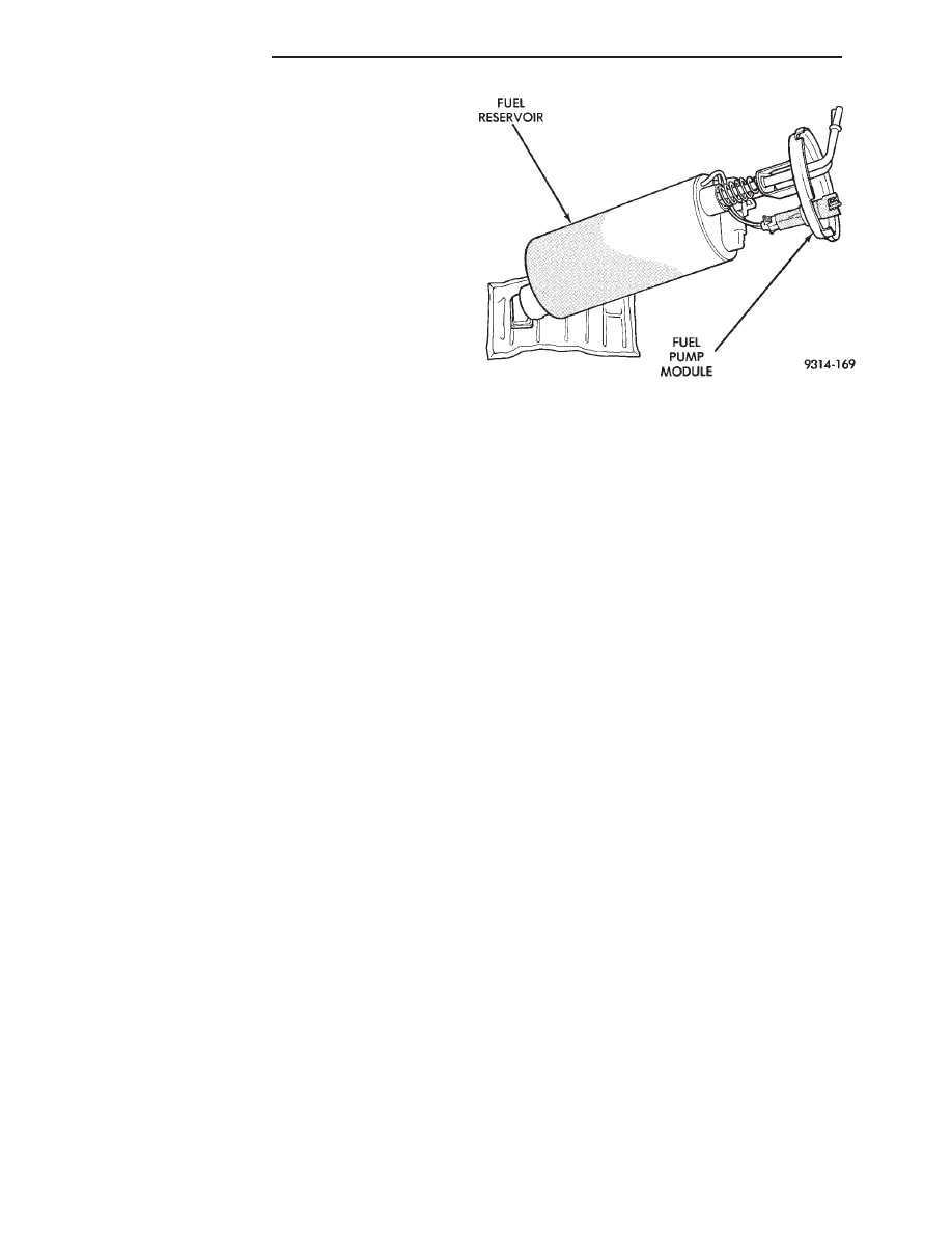
FUEL RESERVOIR
The fuel reservoir is internal to the fuel pump as-
sembly (Fig. 6). The purpose is to provide fuel at the
fuel pump intake during all driving conditions, espe-
cially when low fuel levels are present.
FUEL TANK LEVEL SENSOR
DIAGNOSIS
This procedure test the resistance of the level sen-
sor itself. It does not test the level sensor circuit. Re-
fer to Group 8W, Wiring Diagrams for circuit
identification and Group 8E, Instrument Panel and
Gauges for fuel gauge information.
The level sensor is a variable resistor. Its resis-
tance changes with the amount of fuel in the tank.
The float arm attached to the sensor moves as the
fuel level changes. To test the level sensor, connect
an ohmmeter across the sensor signal and sensor
ground terminals of the fuel level sensor connector
(Fig. 7 or Fig. 8). Move the float lever to the full stop
and empty stop positions shown in the resistance
chart (Fig. 7 or Fig. 8). Record the resistance at each
point. Replace the level sensor if the resistance is not
within specifications.
The low fuel warning light specifications determine
if the level sensor portion of the warning light circuit
functions properly. It does not test the complete
warning light circuit.
Refer to Group 8W, Wiring Diagrams for circuit
identification and Group 8E, Instrument Panel and
Gauges for fuel gauge information.
REMOVAL
WARNING: RELEASE FUEL SYSTEM PRESSURE
BEFORE SERVICING FUEL SYSTEM COMPONENTS.
WHEN
SERVICING
FLEXIBLE
FUEL
VEHICLES,
WEAR METHANOL RESISTANT GLOVES AND EYE
PROTECTION AND AVOID BREATHING FUMES. DO
NOT ALLOW METHANOL/GASOLINE MIXTURES TO
CONTACT SKIN. SERVICE VEHICLES IN WELL VEN-
TILATED AREAS AND AVOID IGNITION SOURCES.
NEVER SMOKE WHILE SERVICING THE VEHICLE.
Fig. 6 Fuel Reservoir
14 - 18
FUEL SYSTEMS
Ä