DAF LF45, LF55 Series. Manual - part 532


  Index      DAF     DAF LF45, LF55 Series - service repair manual


Search            


Content   ..  530  531  532  533   ..


DAF LF45, LF55 Series. Manual - part 532


7

LF45/55 series

Inspection and adjustment

FRONT AXLE, F60

2-7

4.

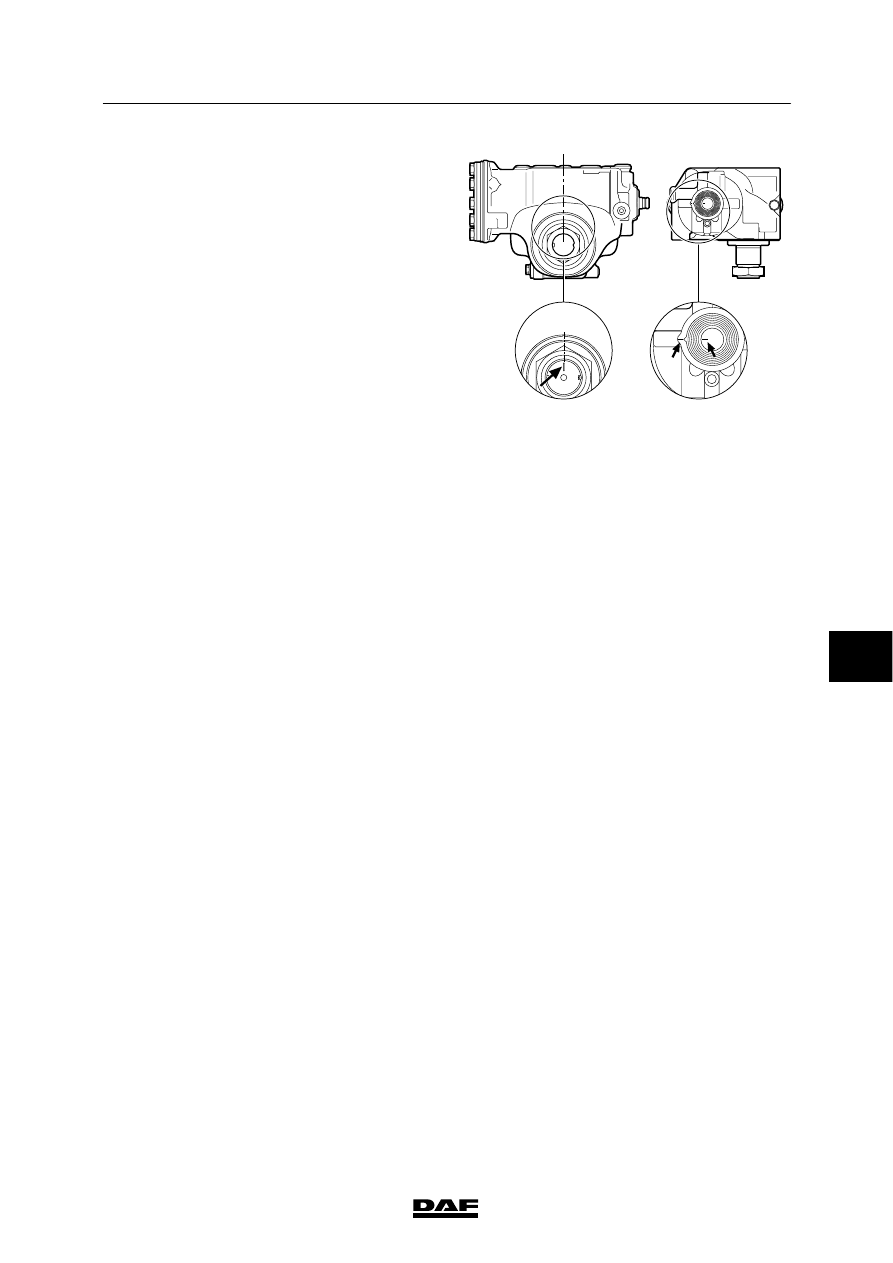
Check that the steering box is exactly in the
central position using the marks in the
steering box. The mark on the input shaft
should be visible in the slot.

5.

Measure the (mis)alignment of the wheel to
which the steering rod is connected. This
can be done using wheel alignment
equipment or by measuring the distance
from the wheel rim to the spring leaves at
the front and rear of the wheel. The
distances at the front and rear of the wheel
must be equal.

6.

Adjust the length of the steering rod, if the
values are different.
If a large difference is measured, the cause
must be traced.
The difference may have been caused by a
collision during which components were
bent. If so, the remaining steering gear
components must be checked carefully.

S7 00 623

Adjusting steering rod
1.

Place the wheel to which the steering rod is
connected in the “straight ahead” position.
This can be done using wheel alignment
equipment or by measuring the distance
from the wheel rim to the spring leaves at
the front and rear of the wheel. The
distances at the front and rear of the wheel
must be equal.

2.

Unscrew the clamping bracket bolt on the
steering rod.

3.

Take the steering rod off the steering-rod
arm using a ball-end puller, see “Removal
and installation”.

7

ᓻ 200322

7

FRONT AXLE, F60

Inspection and adjustment

LF45/55 series

2-8

4.

Place the steering box in the central
position by aligning the marks.

5.

Set the steering rod to the correct length by
screwing the ball end in or out.
If the length is not correct because the ball
end can only be rotated one full turn, get as
close as possible to the correct length.

S7 00 623

Note:
Make sure that the threaded end of the ball
joint is not pushed too far out of the steering
rod. The clamping bracket must always fully
engage the screw thread of the ball joint
(see drawing).

6.

Fit the steering rod in the steering-rod arm,
see “Removal and installation”.

7.

Clean and check the clamping bracket bolt.
If the bolt is corroded or damaged, it must
be replaced.
Replace the self-locking nut.

S7 00 026

8.

Tighten the clamping bracket bolt to the
specified tightening torque, see “Technical
data”.

9.

Check the position of the steering wheel
when it is in the “straight ahead” position. If
necessary, correct the position by changing
the position of the steering wheel on the
steering shaft.

If the vehicle is fitted with an airbag,
observe the warnings and safety
instructions applicable to working
on an airbag system.

7

ᓻ 200322

7

LF45/55 series

Inspection and adjustment

FRONT AXLE, F60

2-9

2.6 CHECKING STEERING BALL JOINT

Checking steering ball joint
1.

Check that the dust cover of the steering
ball joint and its seal is not damaged.
Replace the steering ball joint if they are
damaged.

2.

Check for the presence of the split pin and
its condition.

Checking axial steering ball joint play
1.

Check the axial steering ball joint play using
the special tool (DAF no. 1329426).

2.

Jack up the axle until the wheels are clear
of the floor. Put the axle on stands.

3.

Make sure that the castle nut split pin (if
present) does not come into contact with
the ends of the threaded end.

S7 00 540

4.

Screw the thrust washer (8) onto the
threaded spindle.

5.

Fit the spring retainer (3), spring (4) and
thrust sleeve (6) in the bracket (1).
Fit the locking screw (5). It should be
possible to move the thrust sleeve (6) freely.

Note:
Fit the correct thrust sleeve (6).
The thrust sleeve (6) must abut the rim of
the steering ball joint (7).

6.

Unscrew the thrust bolt (2) until the flange
of the thrust sleeve (6) abuts the bracket
(A=0 mm).

7.

Fit the special tool to the steering ball joint
(7) and turn the threaded spindle (9) by
hand until the special tool is tight around the
steering ball joint (7).

8.

Tighten the thrust bolt (2) until its head
abuts the bracket (1).

9.

Measure the play “A” between the thrust
sleeve and the bracket using a feeler
gauge.
Compare the measurement taken with the
maximum permissible steering ball joint
play, see “Technical data”.
If necessary, replace the steering ball joint.

9

8

7

6

5

4

3

2

A

1

S700426

7

ᓻ 200322

7

FRONT AXLE, F60

Inspection and adjustment

LF45/55 series

2-10

2.7 CHECKING FRONT AXLE HOUSING

General
If the vehicle has been involved in a collision or
if abnormal deviations are measured when the
wheel alignment is checked, it is advisable to
check the axle housing.

A number of the measurements below can also
be carried out using alignment equipment.
Consult the alignment equipment manual for this
purpose.

The special tools required cannot be obtained
from DAF and must be manufactured by
yourself.

S7 00 119

Checking front axle housing
1.

Take the front axle off the vehicle and
remove both swivel axles, see “Removal
and installation”.

2.

Place a straight edge across the spring
seats of the front axle housing and check
whether they are aligned.

S7 00 151

3.

Place a straight edge across both spring
seats and check whether they are parallel
with each other.

S7 00 152

7

ᓻ 200322


Content   ..  530  531  532  533   ..