DAF LF45, LF55 Series. Manual - part 359
5
LF45/55 series
Reading circuit diagrams
READING DIAGRAMS
3-5
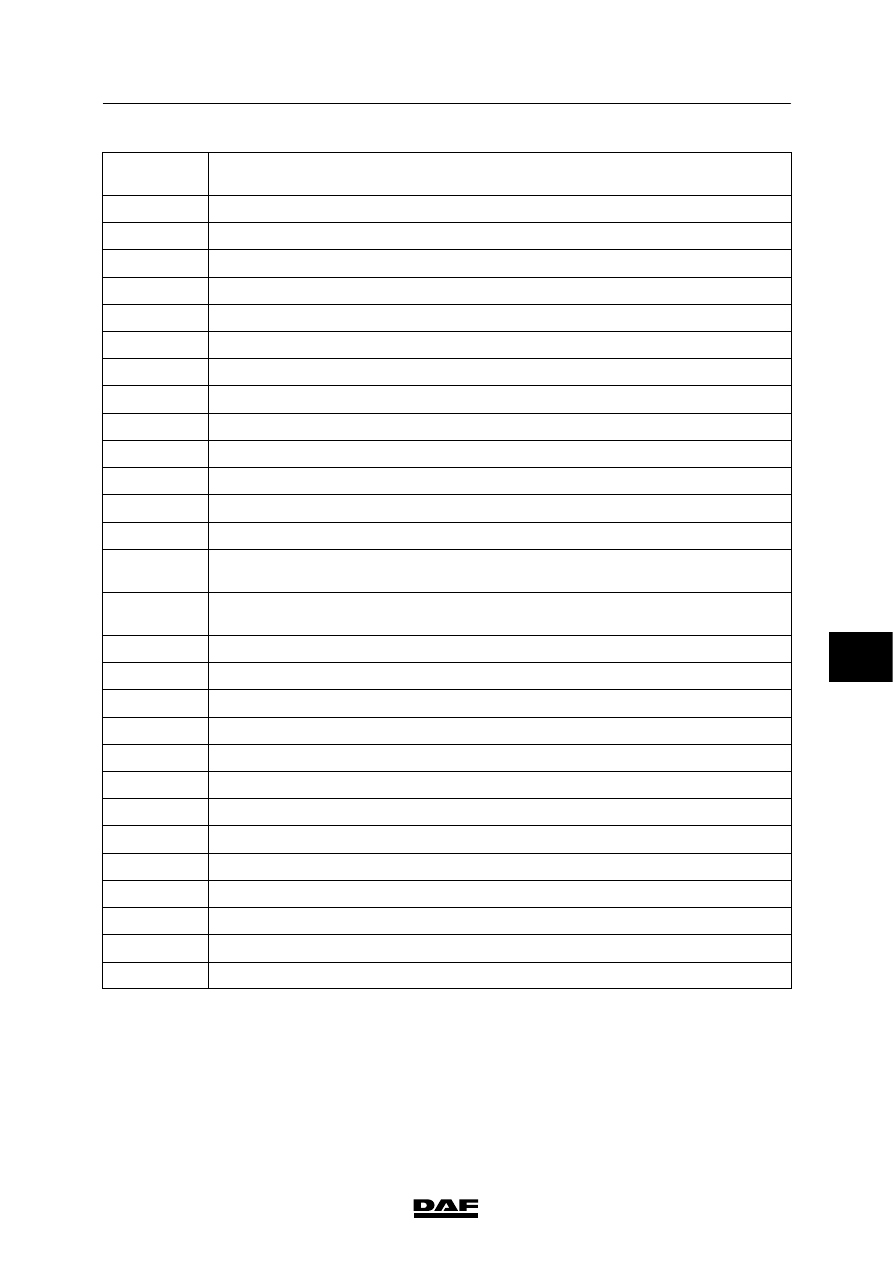
Symbol
number
Description
1
Loudspeaker
2
Electropneumatic or hydraulic valve, 1 driving coil
3
Electropneumatic or hydraulic valve, 2 driving coils
4
Electropneumatic or hydraulic valve, 3 driving coils
5
Diode
6
Bipolar diode
7
LED
8
LED with series resistor
9
4-position switch, key-operated
10
3-position switch with fixed central position, manually operated, spring return
11
Dual 3-position switch with fixed central position, manually operated, spring return
12
Potentiometer with series resistor
13
Potentiometer without series resistor
14
Dual switch; one 2-position switch, manually operated, changeover contact, one
2-position switch, manually operated, contact normally open
15
Dual switch; one 2-position switch, spring return, contact normally open, one
3-position switch, fixed central contact, spring return, changeover contact
16
2-position switch with fixed 0-position, spring return, contact normally open
17
Through-connection
18
Relay with changeover contact
19
Relay with changeover contact
20
Switch, pressure-controlled, dual break, contact normally closed
21
Switch, pressure-controlled, dual break, contact normally open
22
Switch, temperature-controlled, single break, contact normally closed
23
Switch, mechanically operated, dual break, contact normally closed
24
Switch, mechanically operated, dual break, contact normally open
25
Pressure - voltage converter
26
Temperature - voltage converter
27
Revs - pulse converter
28
2-position switch, single break, contact normally open, foot-pedal-operated
7
200440