DAF 95XF. Manual - part 845
1
CAB TILTING MECHANISM
Disassembly and assembly
5-2
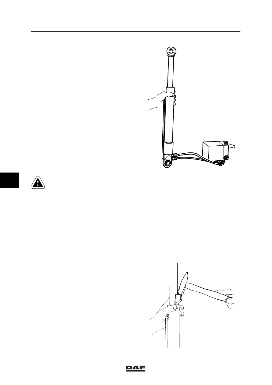
2.
Connect the lifting cylinder to the cab tilting
pump.
K100120
Bleed the lifting cylinder to prevent
the piston rod from moving out of
the lifting cylinder in an
uncontrolled manner after the top
circlip has been removed from the
lifting cylinder.
3.
Bleed the lifting cylinder by pumping out the
piston rod completely. Now turn the lifting
cylinder upside down (connections facing
upwards). Pump the piston rod 15
centimetres inwards. Now turn the lifting
cylinder round again.
4.
Pump the piston rod out approximately
10 mm from the end.
5.
Tap the upper bearing of the piston rod 5 to
10 mm back. Make sure that the piston rod
is not damaged in the process.
k100149
6
ᓻ 0209