DAF 95XF. Manual - part 784


  Index      DAF     DAF 95XF Series - service repair manual


Search            


Content   ..  782  783  784  785   ..


DAF 95XF. Manual - part 784


9

REAR AXLE ALIGNMENT

Inspection and adjustment

2-2

5.

Consult the measuring tool instructions for
use and adhere to them.

6.

Calibrate the measuring tool, if possible.

7.

Use the tool to measure the position of
each rear axle wheel in relation to the
vehicle centreline in mm/m.

8.

Determine the position of the rear axle in
relation to the vehicle centreline on the
basis of the position of the two wheels.

9.

Check that the outcome is within the
permitted tolerance limits. If the
misalignment is beyond these limits, the
axle position must be adjusted.

10. If two or more rear axles are fitted,

determine the position (non-parallelism) of
the rear axles in relation to each other.

11. Check that the outcome is within the

permitted tolerance limits. If the
misalignment (non-parallelism) of the axle is
beyond these limits, the axle position must
be adjusted.

Determining the axle position
A practical aid to visualise the position of the
axle is the measuring report at the end of this
section.
Complete the measuring report as shown below.
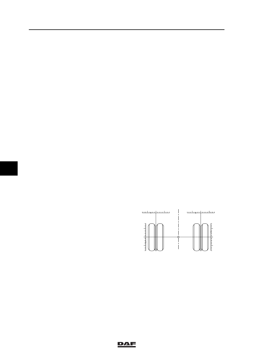
Example 1
1.

Enter the measurement reading in the
scales at the top and side of the measured
wheel.
In the example shown (illustration 1), the
misalignment has been determined to be
3 mm/m toe-out in relation to the vehicle
centreline for the left wheel and 3 mm/m
toe-in relative to the vehicle centreline for
the right wheel.

-

+

+

-

-

+

+

-

3

3

3

3

Afb. 1

w9 08 002

6

ǹ 200316

9

Inspection and adjustment

REAR AXLE ALIGNMENT

2-3

2.

From the small circle at the bottom of the
wheel, draw a straight line to the reading
indicated on the wheel top scale. This
should be done for both wheels
(illustration 2).
The wheel position in relation to the vehicle
centreline is now visible.

-

+

+

-

-

+

+

-

3

3

3

3

w9 08 003

Afb. 2

3.

From the small circle in the middle between
the wheels, draw a straight line to the
reading on the scales at the side of the
wheel. This should be done for both wheels
(illustration 3).
The axle position in relation to the vehicle
centreline is now visible.

-

+

+

-

-

+

+

-

3

3

3

3

Afb. 3

W9 08 004

4.

To realign the axle in this example, it would
have to be rotated 3 mm/m to the right
(illustration 4).

-

+

+

-

-

+

+

-

3

3

3

3

3mm/m

w9 08 005

Afb. 4

6

ǹ 200316

9

REAR AXLE ALIGNMENT

Inspection and adjustment

2-4

Example 2
1.

Enter the measurement reading in the
scales at the top and side of the measured
wheel.
In the example shown (illustration 5), the
misalignment has been determined to be
3 mm/m toe-in relative to the vehicle
centreline for the left wheel and 1 mm/m
toe-out in relation to the vehicle centreline
for the right wheel.

-

+

+

-

-

+

+

-

1

1

3

3

Afb. 5

W9 08 006

2.

From the small circle at the bottom of the
wheel, draw a straight line to the reading
indicated on the wheel top scale. This
should be done for both wheels
(illustration 6).
The wheel position in relation to the vehicle
centreline is now visible.

-

+

+

-

-

+

+

-

1

1

3

3

W9 08 007

Afb. 6

3.

From the small circle in the middle between
the wheels, draw a straight line to the
reading on the scales at the side of the
wheel. This should be done for both wheels
(illustration 7).
The axle position in relation to the vehicle
centreline is now visible.
The illustration shows that this axle is not
entirely straight. The wheels of this axle
have a 2 mm/m toe-in in relation to each
other.

-

+

+

-

-

+

+

-

1

1

3

3

Afb. 7

W9 08 008

6

ǹ 200316

9

Inspection and adjustment

REAR AXLE ALIGNMENT

2-5

4.

Divide the axle toe-in equally over the two
wheels. The toe-in will then be 1 mm/m for
each individual wheel.
Enter this reading on the scales
(illustration 8).

From the small circles under the wheels,
draw dotted lines to the 1 mm/m marking on
the scales (illustration 8).

-

+

+

-

-

+

+

-

1

1

3

3

1

1

W9 08 009

Afb. 8

5.

From the small circle in the middle between
the wheels, draw a dotted line to the
1 mm/m marking on the scale at the side of
the wheel. This should be done for both
wheels (illustration 9).
The ideal position of the rear axle is now
shown by the dotted lines (illustration 9).

6.

To realign the axle in this example, it would
have to be rotated 2 mm/m to the left
(illustration 10).

-

+

+

-

-

+

+

-

1

1

3

3

2mm/m

1

1

1

1

W9 08 011

Afb. 10

6

ǹ 200316


Content   ..  782  783  784  785   ..