DAF 95XF. Manual - part 314
5
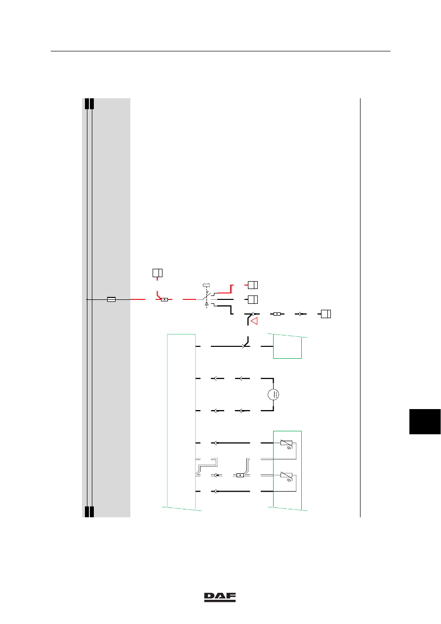
Electrical installation
ELECTRICAL INSTALLATION
2-155
1316630/05
EL000153
41
4001
15/402
1100
1/412
2/412
4/412
6/412
G178
30
1
4002
1130
G178
85
1
4922
4935
4002
10
145
4922
4935
5
383
4002
54
55
56
57
58
59
60
61
62
63
64
65
66
67
68
69
70
71
72
73
74
75
76
77
78
79
80
81
82
83
84
85
86
87
88
89
90
91
92
93
94
96
96
97
98
99
100
101
102
103
104
105
106
9300
9300
9300
12
145
9300
4665
4665
3
145
9300
4935
30
115
4936
4936
6
383
4936
31
115
B068
M
12
G015
85
A
4002
!
4009
4009
27
114
4002
B010
50
A
1100
1100
2
383
B204
3/530
10/530
9/530
4/530
D827
4/
167
1/
166
4/
168
5/
167
10/
167
8/
167
2/
166
D550
45/
232
C539
D878
E037
15A
1010
1000
1010
1000
10
ǹ 9711