Chrysler Town, Dodge Caravan. Manual - part 420


  Index      Chrysler     Chrysler TOWN & COUNTRY, VOYAGER, Dodge Caravan - service repair manual 2001-2007 year


Search            


Content   ..  418  419  420  421   ..


Chrysler Town, Dodge Caravan. Manual - part 420


OIL PUMP

DESCRIPTION

The oil pump is located in the pump housing inside

the bell housing of the transaxle case (Fig. 283). The
oil pump consists of an inner and outer gear, a hous-
ing, and a cover that also serves as the reaction shaft
support.

OPERATION

As the torque converter rotates, the converter hub

rotates the inner and outer gears. As the gears
rotate,

the

clearance

between

the

gear

teeth

increases in the crescent area, and creates a suction
at the inlet side of the pump. This suction draws
fluid through the pump inlet from the oil pan. As the
clearance between the gear teeth in the crescent area
decreases, it forces pressurized fluid into the pump
outlet and to the valve body.

DISASSEMBLY

When disassembling the transaxle it is necessary

to inspect the oil pump for wear and damage.

(1) Remove the reaction shaft support bolts.
(2) Remove reaction shaft support from pump

housing (Fig. 284).

(3) Remove the pump gears (Fig. 285) and check

for wear and damage on pump housing and gears.

(4) Re-install the gears and check clearances.
(5) Measure the clearance between the outer gear

and the pump pocket (Fig. 286). Clearance should be
0.089–0.202 mm (0.0035-0.0079 in.).

(6) Measure clearance between outer gear and

crescent.

Clearance

should

be

0.060-0.298

mm

(0.0023-0.0117 in.).

(7) Measure clearance between inner gear and

crescent.

Clearance

should

be

0.093-0.385

mm

(0.0036-0.0151 in.).

(8) Position an appropriate piece of Plastigage

across both pump gears.

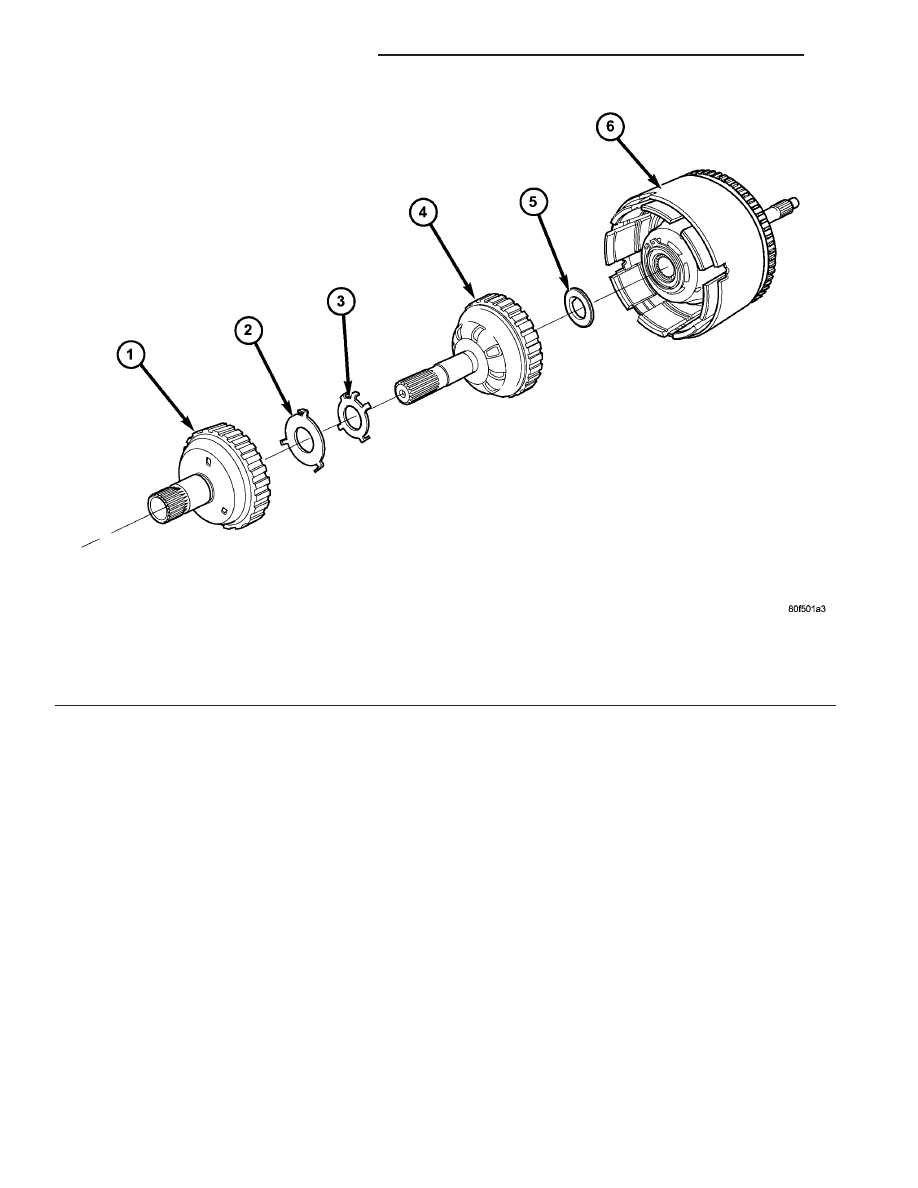
Fig. 282 Overdrive/Underdrive Shafts

1 - OVERDRIVE SHAFT
2 - #3 THRUST PLATE (3 TABS)
3 - #3 THRUST WASHER (5 TABS)

4 - UNDERDRIVE SHAFT
5 - #2 NEEDLE BEARING (3 TABS)
6 - INPUT CLUTCH ASSEMBLY

21 - 230

41TE AUTOMATIC TRANSAXLE

RS

INPUT CLUTCH ASSEMBLY (Continued)

(9) Align the Plastigage to a flat area on the reac-

tion shaft support housing.

(10) Install the reaction shaft to the pump hous-

ing. Tighten the bolts to 27 N·m (20 ft. lbs.).

(11) Remove bolts and carefully separate the hous-

ings. Measure the Plastigage following the instruc-
tions supplied.

(12) Clearance between outer gear side and the

reaction shaft support should be 0.020-0.046 mm
(0.0008-0.0018 in.). Clearance between inner gear
side and the reaction shaft support should be 0.020-
0.046 mm (0.0008-0.0018 in.).

Fig. 283 Oil Pump Assembly

1 - PUMP HOUSING
2 - OUTER PUMP GEAR
3 - INNER PUMP GEAR
4 - REACTION SHAFT SUPPORT
5 - SEAL RINGS (4)
6 - REACTION SHAFT
7 - CRESCENT

Fig. 284 Reaction Shaft Support

1 - PUMP HOUSING
2 - REACTION SHAFT SUPPORT
3 - PUMP GEARS

Fig. 285 Oil Pump Assembly

1 - PUMP HOUSING
2 - OUTER PUMP GEAR
3 - INNER PUMP GEAR
4 - REACTION SHAFT SUPPORT
5 - SEAL RINGS (4)
6 - REACTION SHAFT
7 - CRESCENT

Fig. 286 Measure Outer Gear to Pocket

1 - OUTER GEAR
2 - POCKET

RS

41TE AUTOMATIC TRANSAXLE

21 - 231

OIL PUMP (Continued)

ASSEMBLY

(1) Assemble oil pump as shown in (Fig. 287)
(2) Install and torque reaction shaft support-to-oil

pump housing bolts to 28 N·m (20 ft. lbs.) torque.

PLANETARY GEARTRAIN

DESCRIPTION

The planetary geartrain is located between the

input clutch assembly and the rear of the transaxle
case. The planetary geartrain consists of two sun
gears, two planetary carriers, two annulus (ring)
gears, and one output shaft (Fig. 288).

OPERATION

The planetary geartrain utilizes two planetary gear

sets that connect the transmission input shaft to the
output shaft. Input and holding clutches drive or lock
different planetary members to change output ratio
or direction.

SEAL - OIL PUMP

REMOVAL

(1) Remove transaxle from vehicle (Refer to 21 -

TRANSMISSION/TRANSAXLE/AUTOMATIC - 41TE
- REMOVAL).

(2) Using Tool C-3981-B, remove oil pump seal

(Fig. 289).

Fig. 287 Oil Pump Assembly

1 - PUMP HOUSING
2 - OUTER PUMP GEAR
3 - INNER PUMP GEAR
4 - REACTION SHAFT SUPPORT
5 - SEAL RINGS (4)
6 - REACTION SHAFT
7 - CRESCENT

Fig. 288 Planetary Geartrain

1 - FRONT SUN GEAR ASSEMBLY
2 - #6 THRUST BEARING
3 - #7 THRUST BEARING
4 - REAR CARRIER/FRONT ANNULUS ASSEMBLY
5 - REAR SUN GEAR
6 - FRONT CARRIER/REAR ANNULUS ASSEMBLY

Fig. 289 Remove Oil Pump Seal

1 - TOOL C-3981–B
2 - OIL PUMP SEAL

21 - 232

41TE AUTOMATIC TRANSAXLE

RS

OIL PUMP (Continued)

INSTALLATION

(1) Using Tool C-4193, install oil pump seal (Fig.

290).

(2) Install transaxle to vehicle (Refer to 21 -

TRANSMISSION/TRANSAXLE/AUTOMATIC - 41TE
- INSTALLATION).

SHIFT INTERLOCK SOLENOID

DESCRIPTION

The Brake/Transmission Shift Interlock system

consists of an electro-magnetic solenoid mounted to
the steering column (Fig. 291). The solenoid’s plunger
consists of an integrated hook, which operates the
shift lever pawl (part of shift lever assembly), and a
plunger return spring (Fig. 292). The solenoid also
has an integrated bracket, which facilitates fastening
to the steering column.

OPERATION

The Brake/Transmission Shift Interlock (BTSI) Sole-

noid prevents the transmission shift lever from being
moved out of PARK (P) unless the brake pedal is
applied. The BTSI solenoid is hardwired to and con-
trolled by the Intelligent Power Module (IPM). Battery
voltage is applied to one side of the solenoid with the
ignition key is in either the OFF, ON/RUN, or START
positions (Fig. 293). The ground side of the solenoid is
controlled by a driver within the IPM. It relies on volt-
age supplied from the stop lamp switch to the stop
lamp sense circuit within the IPM to tell when the
brake pedal is depressed. When the brake pedal is
depressed, the ground circuit opens, de-energizing the
solenoid. When the brake pedal is released, the ground
circuit is closed, energizing the solenoid.

When the ignition key is in either the OFF,

ON/RUN, or START positions, the BTSI solenoid is
energized, and the solenoid plunger hook pulls the
shift lever pawl into position, prohibiting the shift
lever from moving out of PARK (P) (Fig. 294). When
the brake pedal is depressed, the ground circuit
opens, de-energizing the solenoid. This moves the
gearshift lever pawl out of the way (Fig. 295), allow-
ing the shift lever to be moved into any gear position.

Fig. 290 Install Oil Pump Seal

1 - TOOL C-4193
2 - HANDLE TOOL C-4171

Fig. 291 Brake/Transmission Shift Interlock (BTSI)

Solenoid Location

1 - BTSI SOLENOID

Fig. 292 Solenoid Plunger and Return Spring

1 - PLUNGER
2 - RETURN SPRING
3 - BTSI SOLENOID

RS

41TE AUTOMATIC TRANSAXLE

21 - 233

SEAL - OIL PUMP (Continued)


Content   ..  418  419  420  421   ..