Chrysler Sebring, Stratus sedan, Sebring Convertible. Manual - part 749


  Index      Chrysler     Chrysler Sebring, Stratus sedan, Sebring Convertible - service repair manual 2001-2007 year


Search            


Content   ..  747  748  749  750   ..


Chrysler Sebring, Stratus sedan, Sebring Convertible. Manual - part 749


EVAP/PURGE SOLENOID

OPERATION

During the cold start warm-up period and the hot

start time delay, the PCM does not energize the sole-
noid. When de-energized, no vapors are purged.

The proportional purge solenoid operates at a fre-

quency of 200 hz and is controlled by an engine con-
troller circuit that senses the current being applied
to the proportional purge solenoid and then adjusts
that current to achieve the desired purge flow. The
proportional purge solenoid controls the purge rate of
fuel vapors from the vapor canister and fuel tank to
the engine intake manifold.
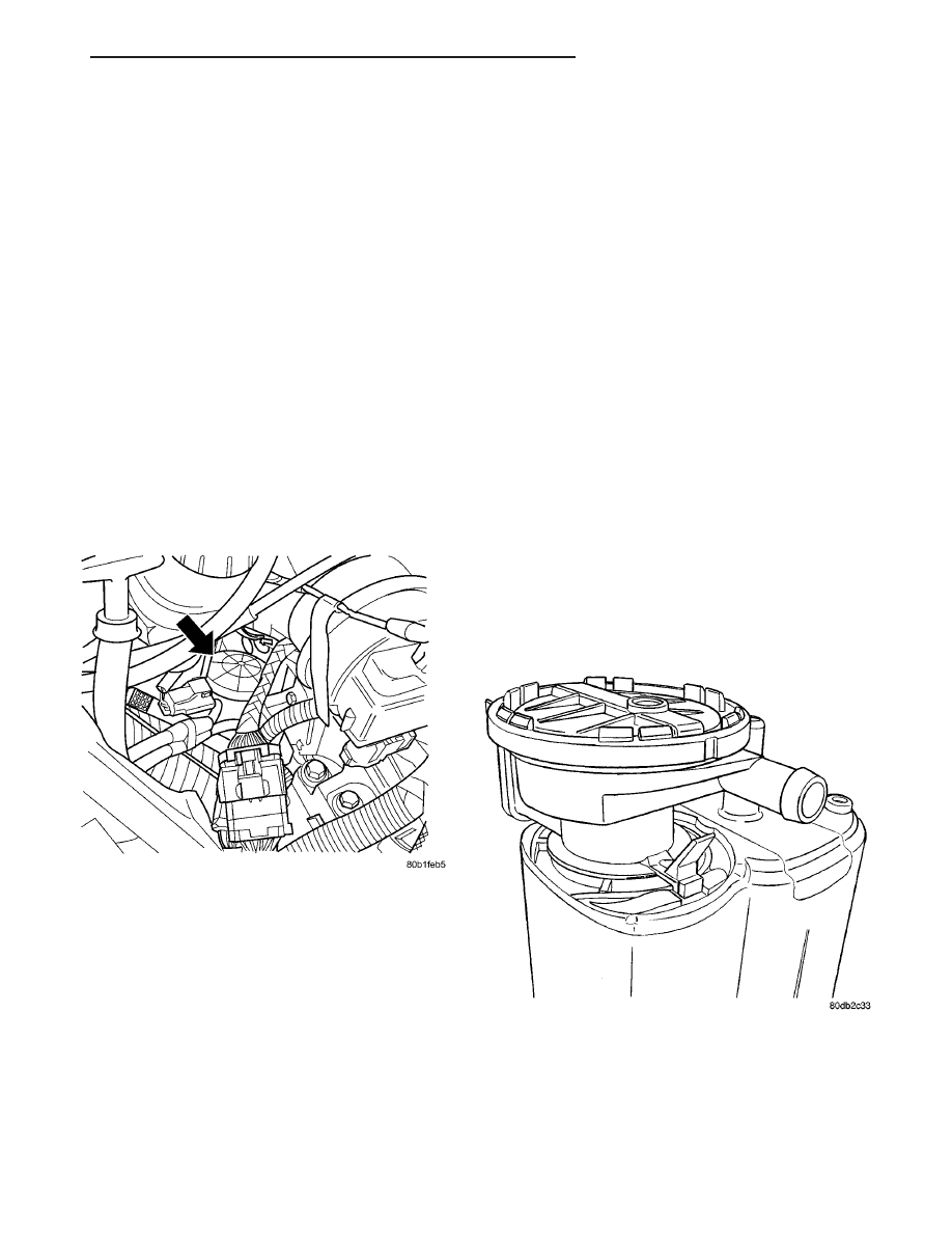
REMOVAL

(1) Disconnect the negative battery cable.
(2) Remove the air cleaner box.
(3) Disconnect the electrical connector.
(4) Disconnect the vacuum hoses.
(5) Remove purge solenoid from the bracket (Fig.

2).

INSTALLATION

(1) Install purge solenoid onto bracket (Fig. 2).
(2) Connect the vacuum hoses.
(3) Connect the electrical connector.
(4) Install the air cleaner box.
(5) Connect the negative battery cable.

FUEL FILLER CAP

DESCRIPTION

The plastic fuel fill cap is threaded/quarter turn

onto the end of the fuel filler tube. It’s purpose is to
retain vapors and fuel in the fuel tank.

OPERATION

The fuel filler cap incorporates a two-way relief

valve that is closed to atmosphere during normal
operating conditions. The relief valve is calibrated to
open when a pressure of 17 kPa (2.5 psi) or vacuum
of 2 kPa (0.6 in. Hg) occurs in the fuel tank. When
the pressure or vacuum is relieved, the valve returns
to the normally closed position.

CAUTION: Remove the fuel filler cap to release fuel
tank pressure before disconnecting any fuel system
component.

NATURAL VAC LEAK
DETECTION ASSY

DESCRIPTION

The natural Vacuum Leak detection (NVLD) sys-

tem is mounted on top of the EVAP canister (Fig. 3)
that is mounted on the fuel tank.

OPERATION

The Natural Vacuum Leak Detection (NVLD) sys-

tem is the next generation evaporative leak detection
system that will first be used on vehicles equipped
with the Next Generation Controller (NGC). This
new system replaces the leak detection pump as the

Fig. 2 PURGE SOLENOID

Fig. 3 NVLD ASSEMBLY

JR

EVAPORATIVE EMISSIONS

25 - 13

method of evaporative system leak detection. This is
to detect a leak equivalent to a 0.020

9 (0.5 mm) hole.

This system has the capability to detect holes of this
size very dependably.

The basic leak detection theory employed with

NVLD is the

9Gas Law9. This is to say that the pres-

sure in a sealed vessel will change if the temperature
of the gas in the vessel changes. The vessel will only
see this effect if it is indeed sealed. Even small leaks
will allow the pressure in the vessel to come to equi-
librium with the ambient pressure. In addition to the
detection of very small leaks, this system has the
capability of detecting medium as well as large evap-
orative system leaks.

A vent valve seals the canister vent during engine

off conditions. If the vapor system has a leak of less
than the failure threshold, the evaporative system
will be pulled into a vacuum, either due to the cool
down from operating temperature or diurnal ambient
temperature cycling. The diurnal effect is considered
one of the primary contributors to the leak determi-
nation by this diagnostic. When the vacuum in the
system exceeds about 1

9 H2O (0.25 KPA), a vacuum

switch closes. The switch closure sends a signal to
the NGC. The NGC, via appropriate logic strategies
(described below), utilizes the switch signal, or lack
thereof, to make a determination of whether a leak is
present.

The NVLD device is designed with a normally open

vacuum switch, a normally closed solenoid, and a
seal, which is actuated by both the solenoid and a
diaphragm. The NVLD is located on the atmospheric
vent side of the canister. The NVLD assembly may
be mounted on top of the canister outlet, or in-line
between the canister and atmospheric vent filter. The
normally open vacuum switch will close with about 1

9

H2O (0.25 KPA) vacuum in the evaporative system.
The diaphragm actuates the switch. This is above the
opening point of the fuel inlet check valve in the fill
tube so cap off leaks can be detected. Submerged fill
systems must have recirculation lines that do not
have the in-line normally closed check valve that pro-
tects the system from failed nozzle liquid ingestion,
in order to detect cap off conditions.

The normally closed valve in the NVLD is intended

to maintain the seal on the evaporative system dur-
ing the engine off condition. If vacuum in the evapo-
rative system exceeds 3

9 to 69 H2O (0.75 to 1.5 KPA),

the valve will be pulled off the seat, opening the seal.
This will protect the system from excessive vacuum
as well as allowing sufficient purge flow in the event
that the solenoid was to become inoperative.

The solenoid actuates the valve to unseal the can-

ister vent while the engine is running. It also will be
used to close the vent during the medium and large
leak tests and during the purge flow check. This sole-

noid requires initial 1.5 amps of current to pull the
valve open but after 100 ms. will be duty cycled down
to an average of about 150 mA for the remainder of
the drive cycle.

Another feature in the device is a diaphragm that

will open the seal in the NVLD with pressure in the
evaporative system. The device will

9blow off9 at

about 0.5

9 H2O (0.12 KPA) pressure to permit the

venting of vapors during refueling. An added benefit
to this is that it will also allow the tank to

9breathe9

during increasing temperatures, thus limiting the
pressure in the tank to this low level. This is benefi-
cial because the induced vacuum during a subse-
quent declining temperature will achieve the switch
closed (pass threshold) sooner than if the tank had to
decay from a built up pressure.

The device itself has 3 wires: Switch sense, sole-

noid driver and ground. The NGC utilizes a high-side
driver to energize and duty-cycle the solenoid.

REMOVAL

(1) Disconnect the negative battery cable.
(2) Remove fuel tank, refer to the Fuel Delivery

section for Fuel Tank Removal.

(3) Disconnect the electrical connector from the

NVLD assembly.

(4) Disconnect the hoses from the NVLD assembly

(Fig. 5).

(5) Lift tab on NVLD assembly (Fig. 4) and twist

the assembly counterclockwise and pull up to remove
from EVAP canister (Fig. 5).

Fig. 4 LOCKING TAB

25 - 14

EVAPORATIVE EMISSIONS

JR

NATURAL VAC LEAK DETECTION ASSY (Continued)

(6) Remove O-ring from EVAP canister (Fig. 6).

INSTALLATION

(1) Install O-ring to EVAP canister (Fig. 6).
(2) Install NVLD assembly (Fig. 4) and twist the

assembly clockwise to lock assembly in the EVAP
canister (Fig. 5).

(3) Connect the hoses to the NVLD assembly.
(4) Connect the electrical connector to the NVLD

assembly.

(5) Install fuel tank, refer to the Fuel Delivery sec-

tion for Fuel Tank Installation.

(6) Connect the negative battery cable.

ORVR

OPERATION

The emission control principle used in the ORVR

system is that the fuel flowing into the filler tube
(appx. 1” I.D.) creates an aspiration effect which
draws air into the fill tube (Fig. 7). During refueling,
the fuel tank is vented to the vapor canister to cap-
ture escaping vapors. With air flowing into the filler
tube, there are no fuel vapors escaping to the atmo-
sphere. Once the refueling vapors are captured by
the canister, the vehicle’s computer controlled purge
system draws vapor out of the canister for the engine
to burn. The vapors flow is metered by the purge
solenoid so that there is no or minimal impact on
driveability or tailpipe emissions.

As fuel starts to flow through the fill tube, it opens

the normally closed check valve and enters the fuel
tank. Vapor or air is expelled from the tank through
the control valve to the vapor canister. Vapor is
absorbed in the canister until vapor flow in the lines
stops, either following shut-off or by having the fuel
level in the tank rise high enough to close the control
valve. The control valve (Refer to 14 - FUEL SYS-
TEM/FUEL DELIVERY/FUEL TANK - OPERATION)
contains a float that rises to seal the large diameter
vent path to the canister. At this point in the fueling
of the vehicle, the tank pressure increases, the check
valve closes (preventing tank fuel from spitting back
at the operator), and fuel then rises up the filler tube
to shut-off the dispensing nozzle.

If the engine is shut-off while the On-Board diag-

nostics test is running, low level tank pressure can
be trapped in the fuel tank and fuel can not be added
to the tank until the pressure is relieved. This is due
to the leak detection pump closing the vapor outlet
from the top of the tank and the one-way check valve
not allowing the tank to vent through the fill tube to
atmosphere. Therefore, when fuel is added, it will
back-up in the fill tube and shut off the dispensing
nozzle. The pressure can be eliminated in two ways:
1. Vehicle purge must be activated and for a long
enough period to eliminate the pressure. 2. Removing
the fuel cap and allowing enough time for the system
to vent thru the recirulation tube.

The Partial Zero Emission Vehicle (PZEV) uses a

hydrocarbon trap on the NVLD to help with trap
hydrocarbon to lower the emission vapors. The NVLD
mounts directly to the top of the trap, and this
assembly mounts to the side of the EVAP canister.

Fig. 5 ASSEMBLY REMOVED

Fig. 6 O-RING

JR

EVAPORATIVE EMISSIONS

25 - 15

NATURAL VAC LEAK DETECTION ASSY (Continued)

Fig. 7 ORVR System Schematic

1 - FUEL TANK (PLASTIC)

11 - NATURAL VACUUM LEAD DETECTION (NVLD)

2 - FUEL FILLER TUBE

12 - LIQUID SEPARATOR (IF EQUIPPED)

3 - FUEL CAP (PRESSURE/RELIEF)

13 - ENGINE WIRING HARNESS TO NVLD

4 - FILL TUBE TO FUEL TANK CONNECTOR (ELASTOMERIC)

14 - VAPOR CANISTER

5 - TANK VENT/ROLLOVER VALVE(S)

15 - PURGE LINE

6 - VAPOR RECIRCULATION LINE

16 - PURGE DEVICE

7 - TANK VAPOR LINE

17 - WITHOUT NVLD

8 - VAPOR LINE TO CANISTER

18 - BREATHER ELEMENT

9 - CHECK VALVE (N/C)

19 - FLOW CONTROL ORIFICE

10 - CONTROL VALVE

20 - SERVICE PORT
21 - WITH NVLD

25 - 16

EVAPORATIVE EMISSIONS

JR

ORVR (Continued)


Content   ..  747  748  749  750   ..