Chrysler Sebring, Stratus sedan, Sebring Convertible. Manual - part 729


  Index      Chrysler     Chrysler Sebring, Stratus sedan, Sebring Convertible - service repair manual 2001-2007 year


Search            


Content   ..  727  728  729  730   ..


Chrysler Sebring, Stratus sedan, Sebring Convertible. Manual - part 729


(2) Remove the accessory drive belt (Refer to 7 -

COOLING/ACCESSORY

DRIVE/BELTS-DRIVE

-

REMOVAL).

(3) Raise and support the vehicle.
(4) Disconnect the wire harness connector from the

clutch field coil connector on the A/C compressor.

(5) Remove the bolts that secure the A/C compres-

sor to the mounting bracket.

(6) Remove the A/C compressor from the mounting

bracket and support the compressor while servicing
the clutch.

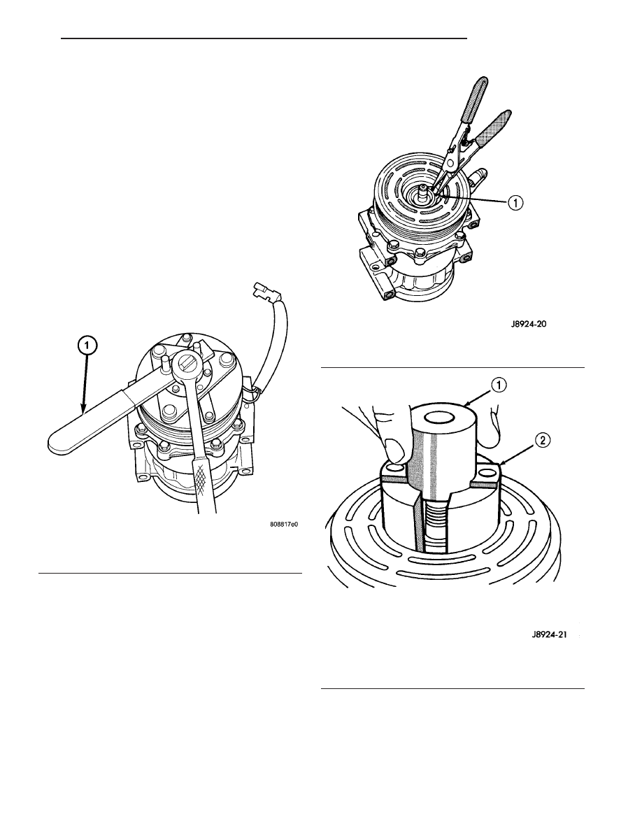
(7) Insert the pins of the spanner wrench (Special

Tool 6462 in Kit 6460) into the holes of the clutch
plate. Hold the clutch plate stationary with the span-
ner wrench and remove the clutch nut (Fig. 6).

(8) Remove the clutch plate with puller (Special

Tool 6461 in Kit 6460).

(9) Remove the clutch shims from the compressor

shaft.

(10) Remove the snap ring that secures the pulley

and bearing assembly to the compressor with snap
ring pliers (Fig. 7).

(11) Install the lip of the puller jaws (Special Tool

6141-1 in Kit 6125) into the front housing hub exter-
nal snap ring groove and install the shaft protector
(Special Tool 6141-2 in Kit 6125) (Fig. 8).

Fig. 6 A/C Clutch - Typical

1 - SPANNER WRENCH

Fig. 7 Front Housing Hub External Snap Ring

1 - SNAP RING

Fig. 8 Shaft Protector and Puller Jaws

1 - SHAFT PROTECTOR
2 - PULLER JAWS

JR

CONTROLS

24 - 15

A/C COMPRESSOR CLUTCH (Continued)

(12) Install the bolts for puller (Special Tool 6461

in Kit 6460) through the puller flange and into the
puller jaws (Fig. 9). Tighten the bolts securely.

(13) Turn the puller center-bolt clockwise until the

pulley and bearing assembly is completely removed
from the front housing hub.

(14) Remove the screw that secures the clutch coil

wire harness retainer clip to the compressor front
housing (Fig. 10).

(15) Remove the snap ring that secures the A/C

clutch field coil to the compressor front housing (Fig.
11).

(16) Remove the clutch field coil from the compres-

sor.

INSPECTION

A/C CLUTCH INSPECTION

NOTE: The A/C clutch can be serviced in the vehi-
cle. The refrigerant system can remain fully-charged
during

compressor

clutch,

pulley

and

bearing

assembly, or coil replacement.

Examine the friction surfaces of the clutch pulley

and the clutch plate for wear (Fig. 12). The pulley
and plate should be replaced if there is excessive
wear or scoring.

If the friction surfaces are oily, inspect the shaft

and nose area of the A/C compressor for refrigerant
oil. If refrigerant oil is found, the compressor shaft
seal is leaking and the A/C compressor must be
replaced.

Check the clutch pulley bearing for roughness or

excessive leakage of grease. Replace the pulley and
bearing assembly, if required.

Fig. 9 Puller and Jaws

1 - BOLT
2 - PULLER AND CENTER-BOLT
3 - BOLT
4 - PULLER JAWS

Fig. 10 Clutch Coil Wire Harness

1 - RETAINER CLIP

Fig. 11 A/C Clutch Field Coil Snap Ring

1 - FIELD COIL
2 - SNAP RING

24 - 16

CONTROLS

JR

A/C COMPRESSOR CLUTCH (Continued)

INSTALLATION

2.4L NA/2.7L ENGINES

(1) Align the A/C clutch field coil squarely onto the

A/C compressor housing front hub.

NOTE: Position the A/C clutch coil so that the coil
positioning tab and the wire harness connector is
oriented in the correct direction.

(2) Install the clutch field coil onto the compressor

with the compressor field coil installer (Special Tool
9352 in Kit 9349), compressor field coil installer
spacer (Special Tool 9353 in Kit 9349) and a two jaw
puller (Fig. 13).

(3) Install the screw that secures the clutch coil

wire harness connector to the compressor housing.
Tighten the screw to 2 N·m (17 in. lbs.).

(4) Align the pulley and bearing assembly squarely

onto the compressor front housing hub.

NOTE: A distinct change of sound during the clutch
pulley tapping process indicates that the pulley and
bearing assembly has bottomed out against the
compressor housing.

(5) Install the pulley and bearing assembly onto

the compressor housing front hub with the clutch
pulley installer (Special Tool 9355 in Kit 9349) (Fig.
14). Tap the installer with a hammer until the pulley

and bearing assembly has bottomed against the com-
pressor housing.

Fig. 12 Clutch Plate and Shim(s) - Typical

1 - A/C COMPRESSOR SHAFT
2 - CLUTCH PLATE
3 - SHIM

Fig. 13 Clutch Field Coil

1 - TWO JAW PULLER
2 - FIELD COIL INSTALLER AND SPACER
3 - WIRE CONNECTOR
4 - CLUTCH FIELD COIL

Fig. 14 Clutch Pulley Installer

1 - CLUTCH PULLEY INSTALLER
2 - PULLEY AND BEARING ASSEMBLY

JR

CONTROLS

24 - 17

A/C COMPRESSOR CLUTCH (Continued)

CAUTION: If the snap ring is not fully seated in the
groove it will vibrate out, resulting in a clutch fail-
ure and severe damage to the front housing of the
compressor.

NOTE: Install the snap ring with the beveled side of
the snap ring facing outward.

(6) Install the snap ring that secures the pulley

and bearing assembly to the compressor. Press the
snap ring to make sure it is properly seated in the
groove.

(7) Verify that there is adequate clearance between

the clutch field coil wire and the clutch pulley.

NOTE: When installing an original, or a new clutch
assembly, try the original shims first. When install-
ing a clutch onto a compressor that previously did
not have a clutch, use 1.0, 0.50, and 0.13 millimeter
(0.040, 0.020, and 0.005 inch) shims from the clutch
hardware package that is provided with the new
clutch.

(8) Install the clutch shims onto the compressor

shaft.

(9) Install the clutch plate and bolt with the com-

pressor clutch holding fixture (Special Tool 9351 in
Kit 9349) (Fig. 15). Hold the clutch plate stationary
with the holding fixture and install the clutch bolt.
Tighten the bolt to 13 N·m (115 in. lbs.).

(10) Check the clutch air gap with a feeler gauge

(Fig. 16). If the air gap does not meet the specifica-
tion, add or subtract shims as required. The air gap
specification is 0.35 to 0.75 millimeter (0.014 to 0.030
inch).

(11) Position the A/C compressor onto the mount-

ing bracket.

(12) Install the bolts that secure the A/C compres-

sor to the mounting bracket. Tighten the bolts to 28
N·m (20 ft. lbs.).

(13) Connect the wire harness to the compressor

clutch field coil connector.

(14) Lower the vehicle.
(15) Install the accessory drive belt (Refer to 7 -

COOLING/ACCESSORY

DRIVE/DRIVE

BELTS

-

INSTALLATION).

(16) Reconnect the negative battery cable.
(17) Perform the Clutch Break-in Procedure (Refer

to 24 - HEATING & AIR CONDITIONING/CON-
TROLS/A/C COMPRESSOR CLUTCH - STANDARD
PROCEDURE).

2.0L AND 2.4L TURBO ENGINE

(1) Position the A/C clutch field coil onto the A/C

compressor front housing.

(2) Install the snap ring that secures the clutch

field coil to the compressor front housing with snap
ring pliers.

Fig. 15 A/C Clutch Bolt

1 - COMPRESSOR CLUTCH HOLDING FIXTURE
2 - CLUTCH BOLT

Fig. 16 Clutch Air Gap

1 - FEELER GAUGE

24 - 18

CONTROLS

JR

A/C COMPRESSOR CLUTCH (Continued)


Content   ..  727  728  729  730   ..